Cabling the provider unit – Allied Telesis AT-MC605 User Manual
Page 42
Overview
42
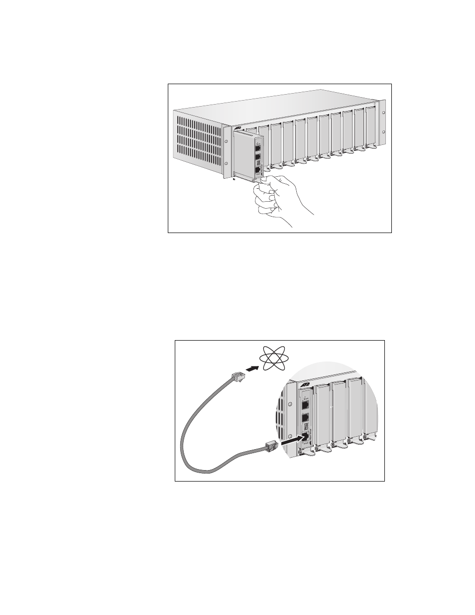
3. Position the slider, as shown in Figure 16 and push into the chassis.
Figure 16. Rack Mount - Set in Rack
4. To connect the cables, see “Cabling the Provider Unit” on page 42.
Cabling the
Provider Unit
To cable the Provider unit, perform the following steps:
1. Connect the ethernet cable from the ethernet port to the Service
Provider box (ISP) in your wiring closet, as shown in Figure 17.
Figure 17. Connecting AT-MC605 Ethernet Port to an Internet Service
Provider
POWE
R
MCR12
V
D
S
L
L
IN
E
1
0
B
a
s
e
-T
/
1
0
0
B
a
s
e
-T
X
P
H
O
N
E
LN
K
/AC
T
10
0M
P
W
R
L
IN
K
RA
T
E
N
O
L
IM
IT
FA
S
T
S
C
B
R
6d
B
RA
TE
L
IM
IT
IN
TL
P
RO
V
9d
B
AT
-M
C
6
0
5
V
D
S
L
E
X
T
E
N
D
E
D
E
T
H
E
R
N
E
T
V
D
S
L
C
O
N
F
IG
PR
O
V
S
C
B
R
1637
MCR12
V
D
S
L
L
IN
E
10B
a
se-T
/
1
00B
as
e-TX
P
H
O
N
E
LNK/
A
CT
100
M
PWR
LIN
K
R
A
TE
N
O
L
IMIT
FA
S
T
S
C
B
R
6d
B
R
A
T
E
L
IM
IT
IN
T
L
P
R
O
V9
d
B
AT
-M
C
605
VDSL EXTENDED ETHERNET
V
D
S
L
C
O
N
F
IG
P
R
O
V
SCBR
1591
Internet
- AT-GS908M (54 pages)
- AT-x230-10GP (80 pages)
- AT-GS950/48PS (64 pages)
- AT-GS950/10PS (386 pages)
- AT-GS950/16PS (386 pages)
- AT-GS950/48PS (386 pages)
- AT-9000 Series (258 pages)
- AT-9000 Series (1480 pages)
- IE200 Series (70 pages)
- AT-GS950/48 (378 pages)
- AT-GS950/48 (60 pages)
- AT-GS950/48 (410 pages)
- AT-GS950/8 (52 pages)
- SwitchBlade x8106 (322 pages)
- SwitchBlade x8112 (322 pages)
- SwitchBlade x8106 (240 pages)
- SwitchBlade x8112 (240 pages)
- AT-TQ Series (172 pages)
- AlliedWare Plus Operating System Version 5.4.4C (x310-26FT,x310-26FP,x310-50FT,x310-50FP) (2220 pages)
- FS970M Series (106 pages)
- 8100L Series (116 pages)
- 8100S Series (140 pages)
- x310 Series (116 pages)
- x310 Series (120 pages)
- AT-GS950/24 (404 pages)
- AT-GS950/24 (366 pages)
- AT-GS950/16 (44 pages)
- AT-GS950/16 (404 pages)
- AT-GS950/16 (364 pages)
- AT-GS950/8 (364 pages)
- AT-GS950/8 (52 pages)
- AT-GS950/8 (404 pages)
- AT-8100 Series (330 pages)
- AT-8100 Series (1962 pages)
- AT-FS970M Series (330 pages)
- AT-FS970M Series (1938 pages)
- SwitchBlade x3106 (288 pages)
- SwitchBlade x3112 (294 pages)
- SwitchBlade x3106 (260 pages)
- SwitchBlade x3112 (222 pages)
- AT-S95 CLI (AT-8000GS Series) (397 pages)
- AT-S94 CLI (AT-8000S Series) (402 pages)
- AT-IMC1000T/SFP (23 pages)
- AT-IMC1000TP/SFP (24 pages)
- AT-SBx3106WMB (44 pages)