Wall-mounting the provider unit – Allied Telesis AT-MC605 User Manual
Page 40
Overview
40
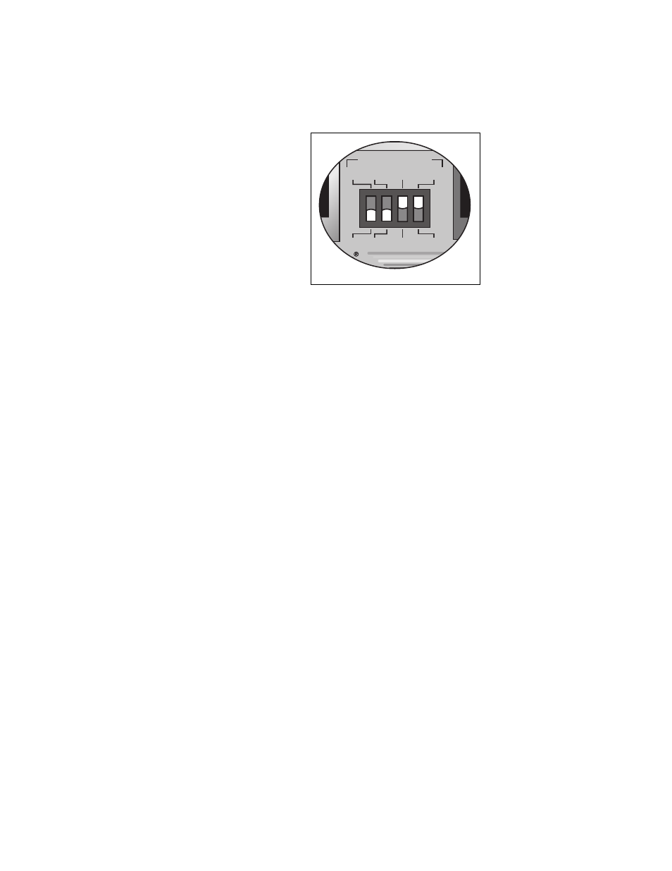
3. Configure the right VDSL CONFIG switch (SCBR/PROV) to the SCBR
position as shown in Figure 13.
Figure 13. Configuring AT-MC605 Ethernet Extender for Provider Mode
4. Go to “Cabling the Provider Unit” on page 42 to connect the cables
and to “Powering On the Provider Unit” on page 44 for powering the
unit.
Wall-Mounting
the Provider Unit
The AT-MC605 VDSL Ethernet Extender may be wall mounted directly to
the wall with an AT-WLMT Wall Mount Bracket or by using an Allied
Telesis DINRAIL Bracket in conjunction with a previously mounted
DINRAIL. Both of these brackets may be ordered separately from the
AT-MC605. Please contact your local Allied Telesis representative.
1. Configure the right VDSL CONFIG switch (SCBR/PROV) to the SCBR
position as shown in Figure 13.
2. Follow the installation instructions supplied with the wall mounting
bracket or DINRAIL bracket.
3. To connect the cables, see “Cabling the Provider Unit” on page 42.
4. To apply power to the unit, see “Powering On the Provider Unit” on
1590
NO LIMIT
FAST
SCBR
6dB
RATE LIMIT
INTL
PROV
9dB
VDSL CONFIG