At-mc605 port descriptions, Vdsl line port, Phone port – Allied Telesis AT-MC605 User Manual
Page 18: Vdsl line port phone port
Overview
18
AT-MC605 Port Descriptions
VDSL Line Port
The VDSL Line port features an RJ-11 connector. It allows you to connect
two AT-MC605 VDSL Ethernet Extender units together using existing
internal building telephone copper pairs. By using this equipment, both
ethernet data and analog phone service are made accessible within a
building without installing additional wiring for the ethernet connections.
One AT-MC605 Ethernet Extender is configured as a Provider unit and the
other as a Subscriber unit. The two units need to be within 3,000 meters
(9842 feet) of each other in order for the port to operate properly.
Table 2 lists the RJ-11 VDSL Line Port pinouts and their assignments.
Phone Port
The Phone Port which allows you to connect one AT-MC605 Ethernet
Extender configured as a Subscriber unit to a telephone and a second AT-
MC605 Ethernet Extender configured as a Provider unit to your private
telephone equipment in the building equipment room. This port features
an RJ-11 connector.
Table 3 lists the RJ-11 Phone Port pinouts and their assignments.
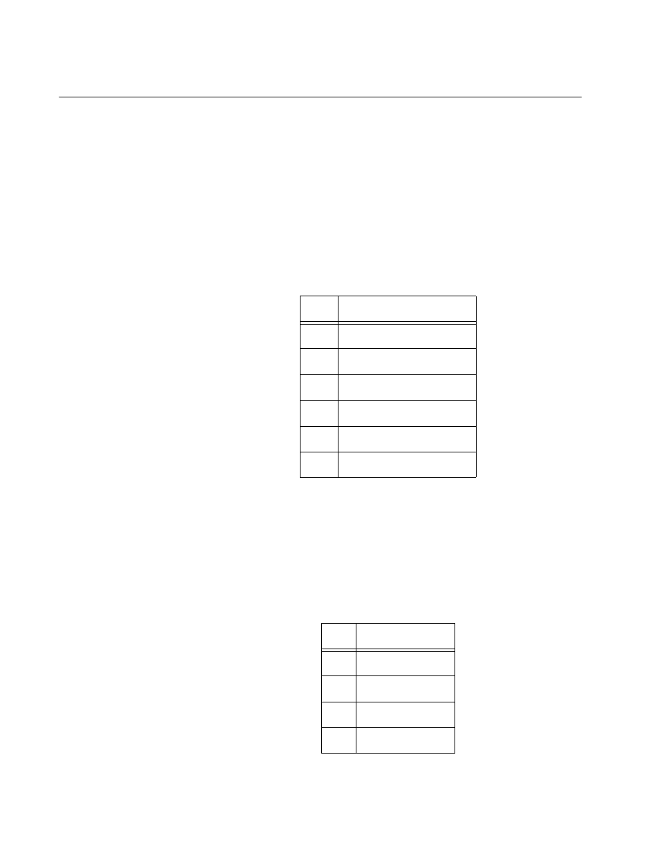
Table 2. RJ-11 VDSL Line Port Pinouts
Pin
Assignment
1
N/C
2
N/C
3
VDSL and phone ring
4
VDSL and phone tip
5
N/C
6
N/C1
Table 3. RJ-11 Phone Port Pinouts
Pin
Assignment
1
N/C
2
N/C
3
phone ring
4
phone tip