Vdsl configuration dip switches, Vdsl switch definitions, Table 6. vdsl configuration dip switches – Allied Telesis AT-MC605 User Manual
Page 24
Overview
24
VDSL Configuration DIP Switches
VDSL Switch
Definitions
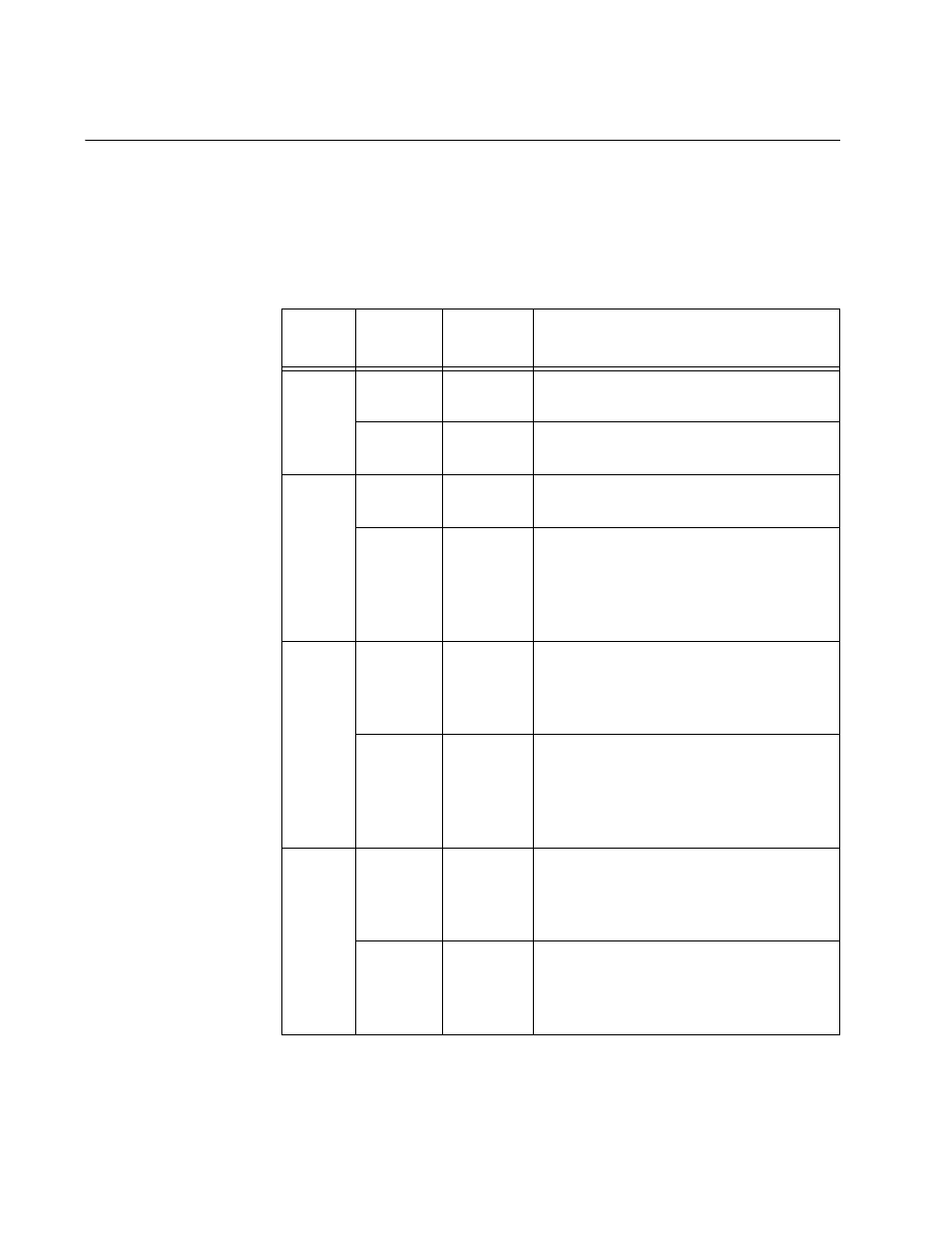
The AT-MC605 VDSL Ethernet Extender features the four VDSL
Configuration DIP switches on the front panel. The UP/DOWN positions of
each switch are shown in “VDSL Configuration DIP Switches” on page 25
and defined in Table 6 below.
Table 6. VDSL Configuration DIP Switches
Switch Position
Switch
Function
Description
Left
UP
SCBR
Unit is configured for the Subscriber
Mode.
DOWN
PROV
Unit is configured for the Provider
Mode.
Left
Center
UP
FAST
FAST mode guarantees a minimum
end to end latency less than 1 ms.
DOWN
INTL
INTL (Interleaved) mode protects
from impulse noises with a duration
less than 250 ms This results in a
maximum end to end latency of less
than 6 ms.
Right
Center
UP
NO
LIMIT
NO LIMIT mode is an asymmetrical
mode which provides line rates of up
to 100 Mbps for the downlink and 60
Mbps for the uplink.
DOWN
RATE
LIMIT
RATE LIMIT mode limits the downlink
and uplink line rates to a symmetrical
mode where the line rates in both
directions are approximately the
same.
Right
UP
6 dB
The unit provides optimum Signal to
Noise Ratio (SNR) for VDSL line
length of less than 305 meters (1000
feet).
DOWN
9 dB
The unit provides optimum Signal to
Noise Ratio (SNR) for VDSL line
length between 305 meters (1000
feet) and 3000 meters (9842 feet).