Wall-mounting the subscriber unit, Cabling the subscriber unit, Overview 36 – Allied Telesis AT-MC605 User Manual
Page 36
Overview
36
5. Go to “Cabling the Subscriber Unit” on page 36 to connect the cables
and to “Powering On the Subscriber Unit” on page 38 for powering the
unit.
Wall-Mounting
the Subscriber
Unit
The AT-MC605 VDSL Ethernet Extender may be wall mounted directly to
the wall with an AT-WLMT Wall Mount Bracket or by using an Allied
Telesis DINRAIL Bracket (both supplied separately) in conjunction with a
previously mounted DINRAIL.
1. Configure the right VDSL CONFIG switch (SCBR/PROV) to the SCBR
position as shown in Figure 7, ”Configuring AT-MC605 Ethernet
Extender for Subscriber Mode” on page 35.
2. Follow the installation instructions supplied with the wall mounting
bracket.
3. Go to “Cabling the Subscriber Unit” on page 36 to connect the cables
and to “Powering On the Subscriber Unit” on page 38 for powering the
unit.
Cabling the
Subscriber Unit
To cable the Subscriber unit to a computer or telephone, perform the
following steps:
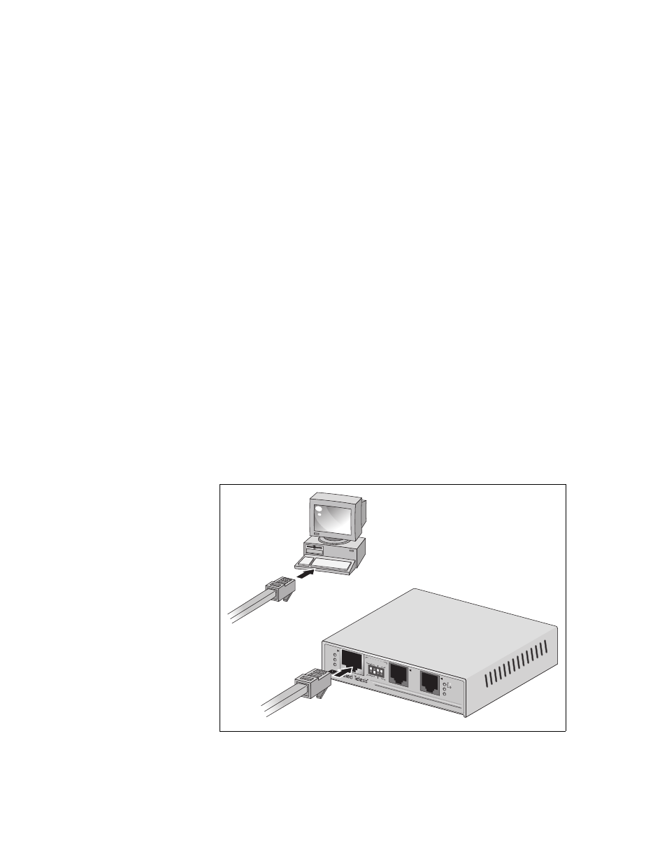
1. To connect a computer to the AT-MC605 Ethernet Extender, connect
the ethernet cable from the AT-MC605 ethernet port to the ethernet
port on your computer, as shown in Figure 8 , ”Connecting AT-MC605
Ethernet Port to Computer”.
Figure 8. Connecting AT-MC605 Ethernet Port to Computer
VDSL LIN
E
10Base-T
/
100Base
-TX
PHONE
LNK/ACT
100M
PWR
LINK
RATE
NO LIMIT
FAST
SCBR
6dB
RATE LIM
IT
INTL
PROV
9dB
AT-MC605
VDSL EX
TENDE
D ETHERN
ET
VDSL C
ONFIG
PROV
SCBR
1558