10/100/1000base-t twisted-pair port connectors, Figure 35. rj-45 connector and port pin layout, Table 7: mdi pin signals (10base-t or 100base-tx) – Allied Telesis AT-2912T User Manual
Page 93
Secure Ethernet Network Adapter Installation and User’s Guide
93
Receive Sensitivity:
-12.5 dBm with 62.5 um fiber or
-13.5 dBm with 50 um fiber
AT-2712LX20/SC Operating Specifications:
Output Optical Power:
-15 dBm minimum to -5 dBm maximum
Input Optical Power:
-3 dBm maximum
Receive Sensitivity:
-34 dBm typical
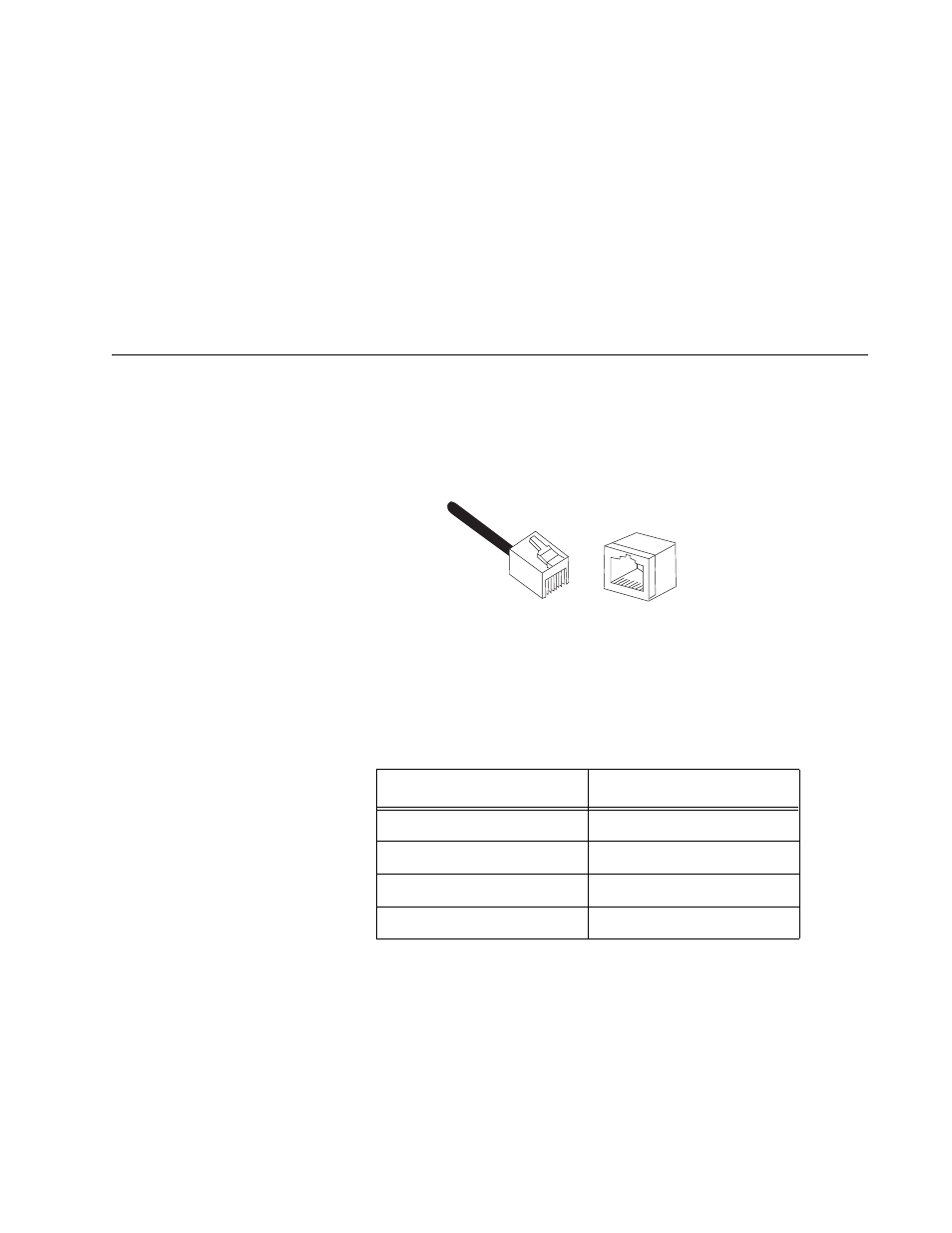
10/100/1000Base-T Twisted-Pair Port Connectors
This section lists the pin signals for the 10/100/1000Base-T twisted-pair
ports for the AT-2912T adapter. Figure 35 illustrates the pin layout to an
RJ-45 connector and port.
Figure 35. RJ-45 Connector and Port Pin Layout
Table 6 lists the RJ-45 pin signals when a twisted-pair port is operating in
the MDI configuration.
Table 6. MDI Pin Signals (10Base-T or 100Base-TX)
Pin
Signal
1
TX+
2
TX-
3
RX+
6
RX-
8
8
1
1
This manual is related to the following products: