Connecting the network cables – Allied Telesis AT-2912T User Manual
Page 33
Secure Ethernet Network Adapter Installation and User’s Guide
33
Connecting the Network Cables
The AT-2712FX/SC and AT-2712LX20/SC adapters have two fiber optic
connectors (transmit and receive) for attaching the system to a compatible
link partner or an IEEE 802.3z compliant Fast Ethernet switch. Both
adapters require a fiber optic cable.
The AT-2912T adapter has one twisted-pair connector which requires a
twisted-pair cable. For pin signals and pinout information, see “10/100/
1000Base-T Twisted-Pair Port Connectors” on page 93.
To connect a network cable to the adapter, perform the following
procedure:
Warning
The fiber optic ports contain a Class 1 LED device. When the ports
are disconnected, always cover them with the provided plug.
Exposed ports may cause skin or eye damage
.
1. Connect one end of the cable to the adapter:
For the AT-2912T adapter, connect one end of the twisted-pair
cable to the adapter.
For the AT-2712FX/SC and AT-2712LX20/SC adapters, prepare a
fiber optic cable according to the specifications in Table 3. Connect
one end of the cable to the adapter.
2. Connect the other end of the cable:
For the AT-2912T adapter, connect the other end of the cable to
another twisted pair port.
For the AT-2712FX/SC and AT-2712LX20/SC adapters, connect
the other end of the cable to the appropriate Ethernet fiber optic
port.
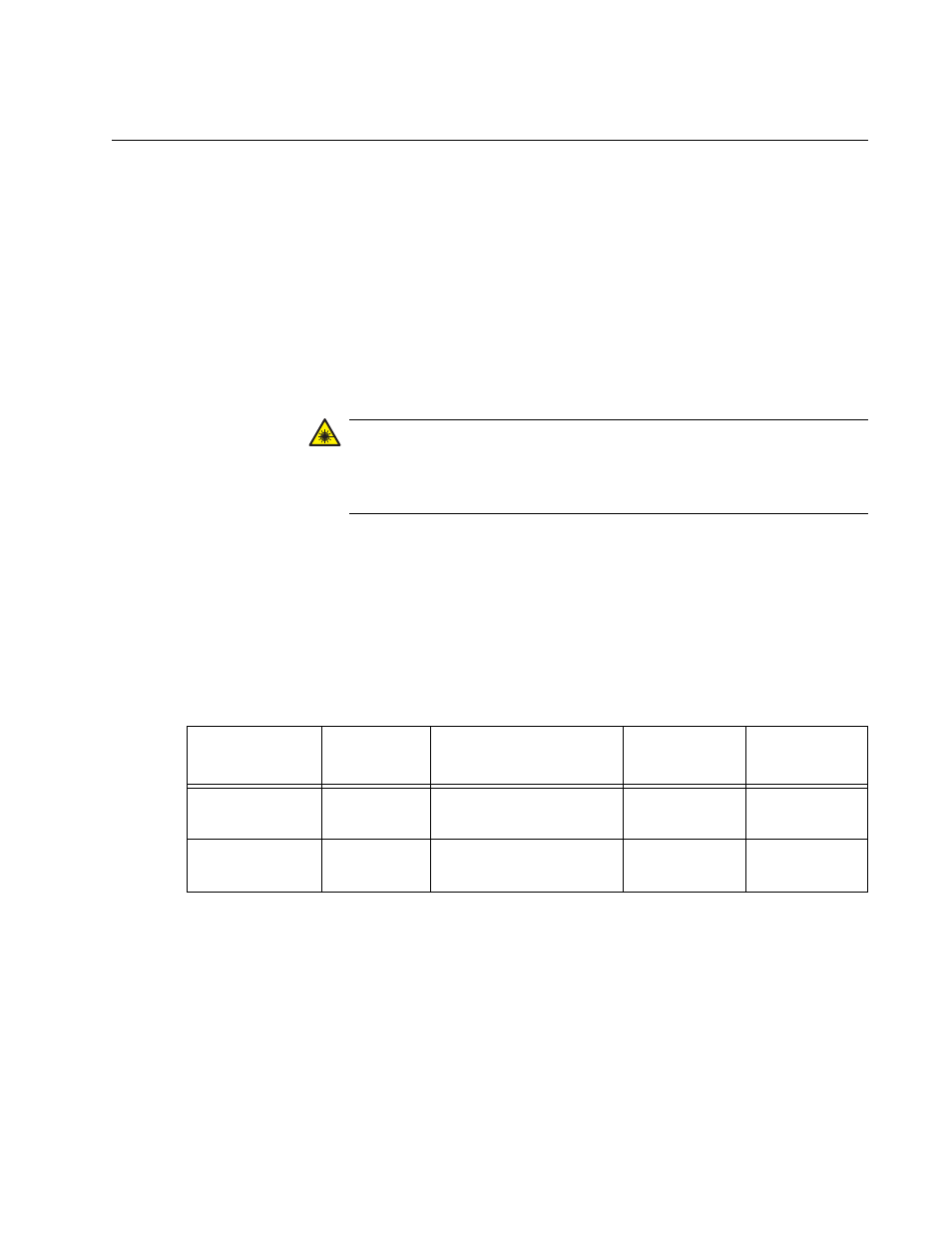
Table 3. 1000BASE-SX Fiber Optic Cable Specifications
Port Type
Connector
Media
Maximum
Distance
Wavelength
1000BASE-SX
Fiber Optic
62.5 µm multimode
850 nm
275 meters
(853 feet)
1310 nm
1000BASE-LX
Fiber Optic
9.125 µm single mode
1310 nm
10 kilometer
(6.213 miles)
1310 nm