Figure 18: removing the rubber feet from a switch, Turn the switch back over, Igure – Allied Telesis AT-x230-18GP User Manual
Page 55: Emoving, Rubber, Feet, From, Switch
AT-x230-10GP and AT-x230-18GP Switches Installation Guide
45
Installing an AT-x230-18GP switch in an equipment rack
These instructions show you how to install an AT-x230-18GP switch in an
equipment rack. Rack mount kits for the AT-x230-18GP switch, AT-RKMT-
J13, can be purchased separately from your Allied Telesis dealer.
To install an AT-x230-18GP switch in a 19-inch equipment rack, follow
these steps:
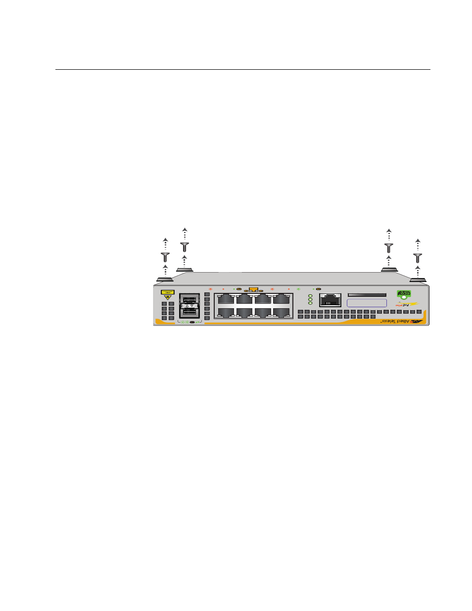
1. If rubber feet are attached to the base of the switch, place the unit
upside down on a level, secure surface.
2. Remove the rubber feet with a screwdriver (Figure 18).
F
IGURE
18. R
EMOVING
THE
RUBBER
FEET
FROM
A
SWITCH
x230-10GP
CONSOLE
RS-232
SD
FAUL
T
POWER
SD
1000 LINK
ACT
10/100 LINK
ACT
PD ON
PD ERR
MAX CURRENT
SFP
9
10
2
4
6
8
1
3
5
7
MAC A
ddress Label
3. Turn the switch back over.