Figure 8: fault led on an x230 series switch, Fault led, 10gp – Allied Telesis AT-x230-18GP User Manual
Page 33
AT-x230-10GP and AT-x230-18GP Switches Installation Guide
23
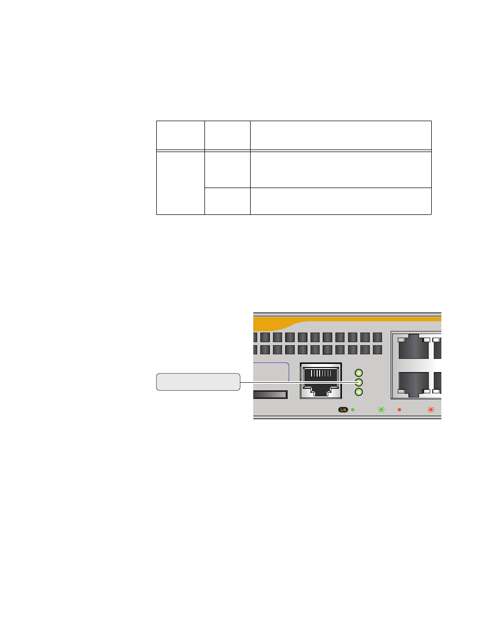
Table 4 describes the POWER LED for the AT-x230-10GP and AT-x230-
18GP switches.
Figure 8 shows the location of the FAULT LED.
F
IGURE
8. FAULT LED
ON
AN
X
230 S
ERIES
S
WITCH
10GP
CONSOLE
RS-232
SD
FAULT
POWER
D
1000 LINK
ACT
10/100 LINK
ACT
2
1
ess Label
Fault LED
T
ABLE
4. AT-
X
230-10GP
AND
AT-
X
230-18GP POWER LED
FUNCTIONAL
DESCRIPTIONS
LED
State
Description
POWER
Off
Indicates either the switch is not receiving
AC power or the AC input power is operating
outside the normal range
Steady
green
The switch is receiving AC input power and is
operating normally
This manual is related to the following products: