Allied Telesis AT-x230-18GP User Manual
Page 34
Chapter 1: Overview
24
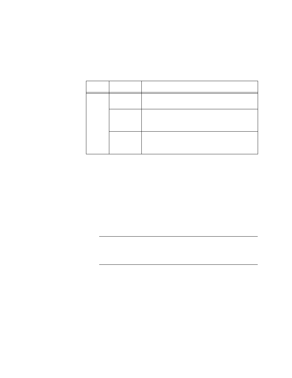
Table 5 describes the functions of the FAULT LED for the AT-x230-10GP
and AT-x230-18GP switches.
T
ABLE
5. AT-
X
230-10GP
AND
AT-
X
230-18GP FAULT LED
FUNCTIONAL
DESCRIPTIONS
LED
State
Description
The switch is receiving AC input power and is
operating normally
Indicates fan failure
Indicates the switch’s temperature has
exceeded the threshold
10/1000BASE-T/
100BASE-TX
Link/Activity/
Speed LED and
PoE status LED
The Link/Activity/Speed and PoE LEDs provide information about the 10/
1000BASE-T and the 100BASE-TX ports.
The AT-x230-10GP and AT-x230-18GP switches indicate Link/Activity/
Speed and PoE status with two LEDs for each port (Figure 9 and Figure
10). For each port:
the left LED corresponds to Link/Activity/Speed
the right LED corresponds to PoE status
Note
All of the port LEDs are OFF when the switch is operating in the low
power mode. To toggle on the LEDs, use the ecofriendly button. See
“ecofriendly button” on page 30 for more information.
FAULT
Off
Red
flashing
once
Red
flashing six
times