Campbell Scientific TurfWeather Weather Station User Manual
Page 63
TurfWeather Weather Station
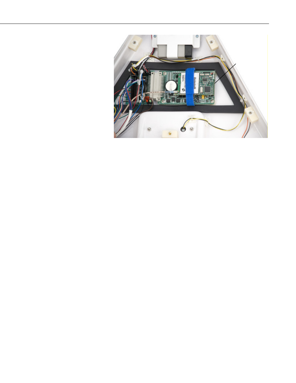
FIGURE 6-9. Main electronics board inside TurfWeather station
f. Rest the base section next to the electronics section and locate the
main electronics board within the electronics section (FIGURE 6-9).
It is the largest green rectangular electronics board in the weather
station electronics section.
g. Locate the screws at the corners of the main electronics board and
touch one finger to one of the screws. Touching the screw will
ground any electrostatic energy difference between you and the
weather station main electronics board. Do not be concerned, as this
will not shock you or create a spark.
h. Remove the four Phillips head screws that attach the main electronics
board to the weather station electronics section.
i. Notice the gray plastic connector on one end of the main electronics
board. This connects the board to the adjacent sensor connector
board. Grasp both the main electronics board and the sensor
connector board near the connector and gently pull them apart at the
mating connector. You may need to use a slight side-to-side motion
to separate the connector.
j. If you received a replacement main electronics board, it was shipped
in a special ESD protective bag. Remove the replacement main
electronics board from this bag and put the board you removed from
your weather station into the same ESD bag.
2. Main Electronics Board Replacement:
a. If your weather station is wireless, the replacement main electronics
will have a spread spectrum radio board attached to it with a blue
Velcro strap. The main carrier frequency for the radio board is printed
on the white label with the word MaxStream. It will be either 900
MHz or 2.4 GHz. Verify that the carrier frequency is the same as that
Main Electronics
Board
53