9 17342 short-haul modem installation, 17342 short-haul modem installation – Campbell Scientific TurfWeather Weather Station User Manual
Page 38
TurfWeather Weather Station
3. Principle of Operation:
a. A Yagi high gain antenna is a directional RF device designed to
minimize signal attenuation at the base station location, thereby
providing the maximum available energy at the antenna for
communication with the remotely located weather station. This
antenna needs to be aimed and the best result is obtained with a clear
line-of-sight to the remote transceiver. If you can see the weather
station, the system has a clear line-of-sight.
b. The Polyphaser senses the presence of a high voltage electrostatic
energy pulse and passes it to earth ground before it can damage the
radio.
4. System Test:
a. Initiate the system software and verify that the radio will
communicate with the weather station. See Section 4, Quickstart
Guide.
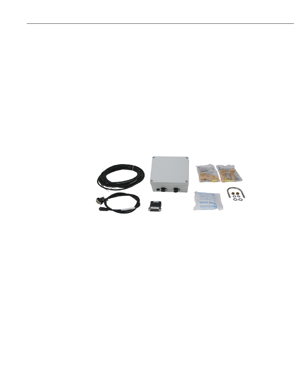
5.4.9 17342 Short-Haul Modem Installation
1. Attach the enclosure from 17342 kit onto the tripod or mounting pipe
under the TurfWeather weather station using the supplied U-bolts. Mount
this underneath or opposite of the solar panel if used to prevent shadowing
on the solar panel (FIGURE 5-16).
2. Connect the 17326 cable to the connector on the bottom of the enclosure
marked
WEATHER STATION. Connect the other end of this cable to
the bottom of the weather station marked
RS-232 and thread the thumb
screws into the connector to secure the cable connector to weather station
(FIGURE 5-17 and FIGURE 5-18).
3. Connect the 12002 cable to the connector on the bottom of the enclosure
marked
COMPUTER. The other end of this cable has a red wire labeled
+RCV, a black wire labeled –RCV, a green wire labeled +XMT, and a
white wire labeled
–XMT. Connect these wires to the customer-supplied
cable using the direct burial splice kits. The wire used from the user-
supplied cable to connect to the red
+RCV wire should be connected to the
terminal marked
+RCV on the short haul modem used on the computer
end of cable run. The remaining wires should follow the same procedure
so that each wire is connected to the corresponding terminal on the short
haul modem.
28