4 installation of the radiation shields, 5 instrument-inversion-test, Datalogger programming – Campbell Scientific NR01 Net Radiometer User Manual
Page 24
NR01 Four-Component Net Radiation Sensor
4.4 Installation of the Radiation Shields
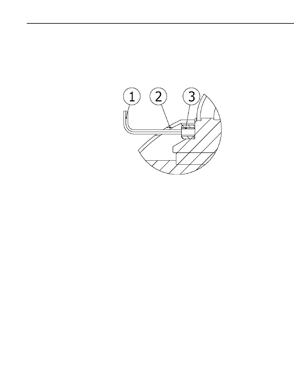
Radiation shields can be installed and removed using a hex-head wrench (bolt
size 2.0 mm). See the drawing below. Radiation shields are beneficial for
instrument measurement accuracy and instrument and cable lifetime. They also
serve as rain- and snow shield. However, the instrument should function within
specifications without the radiation shield.
FIGURE 4.4-1. Installation and Removal of Radiation Shields:
(1) Hex-Head Wrench, (2) Radiation Screen
(3) Hexagon Drive Set Screw
4.5 Instrument-Inversion-Test
Campbell Scientific recommends performing the instrument-inversion test after
installation. This test consists of inverting the instrument position (180 degrees
turn) and looking at the output signals. The instrument output should have the
same magnitude but a reversed sign (so + to – and – to +). For best results,
perform this test on a clear day—preferably around noon (with the sun high in
the sky).
Roughly speaking, deviations within ±10% can be tolerated. For optimal
testing of pyrgeometers, the test should be repeated on a clear night.
5. Datalogger Programming
The NR01 outputs four voltages that typically range from 0 to 50 mV for the
SR01 sensors, and
±5 mV for the IR01 sensors. A differential voltage
measurement (VoltDiff in CRBasic or Instruction 2 in Edlog) is recommended
because it has better noise rejection than a single-ended measurement. If
differential channels are not available, a single-ended measurement (VoltSE or
Instruction 1) can be used. The acceptability of a single-ended measurement
can be determined by simply comparing the results of single-ended and
differential measurements made under the same conditions.
20