Campbell Scientific NR01 Net Radiometer User Manual
Page 21
NR01 Four-Component Net Radiation Sensor
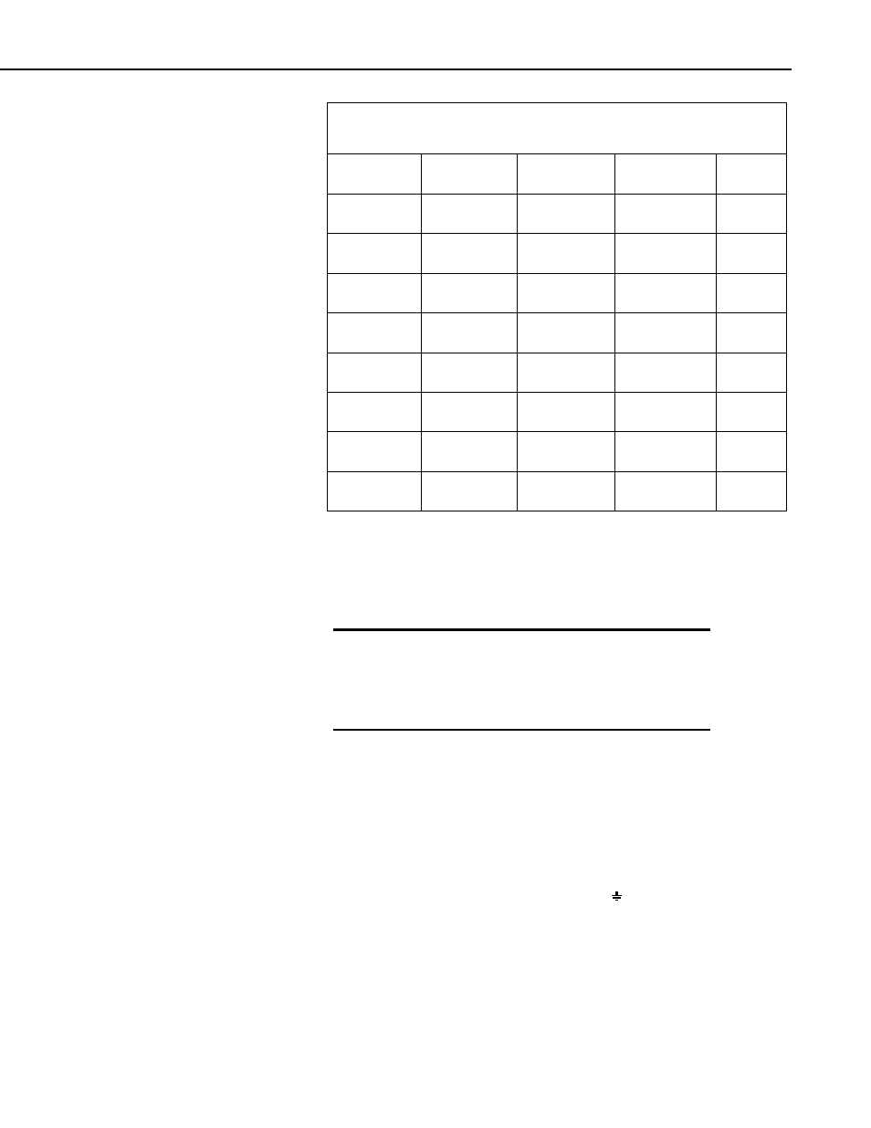
TABLE 4.2-1. Internal Electrical Diagram of the NR01
(for servicing purposes only)
PCB04
Connection
PCB04
Terminal
PCB05
Connection
PCB05
Terminal
Polarity
3
8
Pyrgeometer
UP
-
4
7
Pyrgeometer
UP
+
5
12
Pyrgeometer
DOWN
-
6
11
Pyrgeometer
DOWN
+
13
Pyranometer
UP
+
14
Pyranometer
UP
-
9
Pyranometer
DOWN
+
10
Pyranometer
DOWN
-
Table 4-2 shows the NR01 wiring connections for the four radiation outputs,
Pt-100 temperature sensor, and the heater. Table 4.2-1 shows the internal
connections to the terminal blocks, which should only be required for
servicing, e.g. cable replacement.
The sensor has two cables with similar color schemes.
It is important to make sure you identify cable 1 and
cable 2 correctly, especially before connecting any
source of power such as to the heater. Failure to do
so may damage the sensor.
WARNING
4.3 Connecting the Sensor to Campbell Scientific Dataloggers
This section shows the typical connection schemes.
The four radiation outputs can be measured using Differential (Table 4.3-1) or
Single-Ended inputs on the datalogger (Table 4.3-2). A differential voltage
measurement (VoltDiff or Instruction 2) is recommended because it has better
noise rejection than a single-ended measurement. When differential inputs are
used, jumper the low side of the input to AG or
to keep the signal within
the common mode range.
17