1 connecting and using the heater – Campbell Scientific NR01 Net Radiometer User Manual
Page 23
NR01 Four-Component Net Radiation Sensor
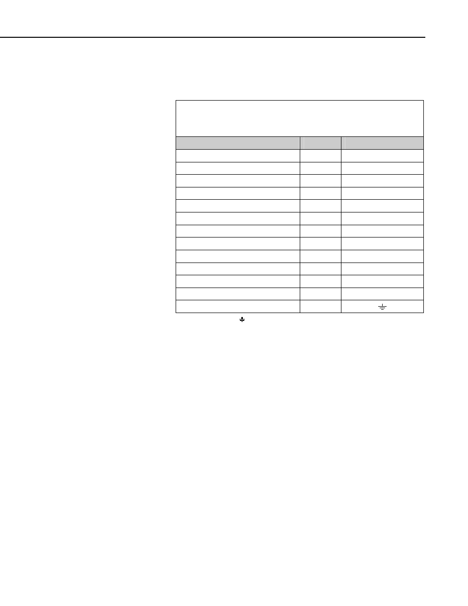
The PT-100 sensor can connect directly to the CR3000 and CR5000
dataloggers because they have current excitation outputs. Refer to Table 4.3-4
and Program Example 5.2.2 for information on using the current excitation
technique with a CR3000 or CR5000 datalogger.
TABLE 4.3-4. CR3000 and CR5000 Connections
for Differential Measurement and using the Current Excitation to
Measure the PT100 Sensor
Wire Label
Color
CR3000/CR5000
Pyranometer Up Sig
Red
Differential Input (H)
Pyranometer Up Ref
*Blue
Differential Input (L)
Pyranometer Down Sig
White
Differential Input (H)
Pyranometer Down Ref
*Green
Differential Input (L)
Pyrgeometer Up Sig
Brown
Differential Input (H)
Pyrgeometer Up Ref
*Yellow
Differential Input (L)
Pyrgeometer Down Sig
Purple
Differential Input (H)
Pyrgeometer Down Ref
*Grey
Differential Input (L)
PT100 Signal
**White
Differential Input (H)
PT100 Signal Ref
**Green
Differential Input (L)
Current Excite
**Red
Current Excitation IX
Current Return -
**Blue
Current Excitation IXR
Shield (both cables)
Clear
*Jumper to AG or
with user-supplied wire.
**Note these are in Cable 2.
4.3.1 Connecting and Using the Heater
Only use the sensor heater when there is risk of dew forming on the sensors,
especially for low power installations. Furthermore, the heater should be
turned on and off infrequently as it may take some time for the sensor to come
to thermal equilibrium. No damage will result if the heater is powered
permanently, but as with all thermopile sensors, it is best if the sensor operates
at ambient temperatures and is not subject to rapidly changes of temperature.
The sensor power can be controlled using one of the 12V power switches built
into Campbell dataloggers or using an external solid-state switch such as a
PSW12/SW12. The heater current drain is approximately 140 mA from a 12 V
battery. Connect the ground return from the heater, either directly to the
battery, or to a G terminal close the power input to the logger (i.e., not to an
analog ground near the measurement inputs).
The heater power can be controlled by adding instructions to the datalogger
program, that turns on the heater only when the light level falls below 20 W m
-
2
or, if a measurement of air humidity is available, when the dew point of the
air falls to within 1ºC of the sensor body temperature. Appendix A provides an
example CR3000/CR5000 program that controls the NR01 heater.
19