2 electrical connections – Campbell Scientific NR01 Net Radiometer User Manual
Page 20
NR01 Four-Component Net Radiation Sensor
4.2 Electrical Connections
The NR01 is a passive sensor that does not need any power. However there is
an on-board heating resistor in the pyrgeometer connection body that may be
switched on to prevent dew deposition.
Cables generally act as a source of signal distortion by picking up capacitively
coupled noise. Campbell Scientific generally recommends keeping the distance
between the datalogger and sensor as short as possible. For cable extension,
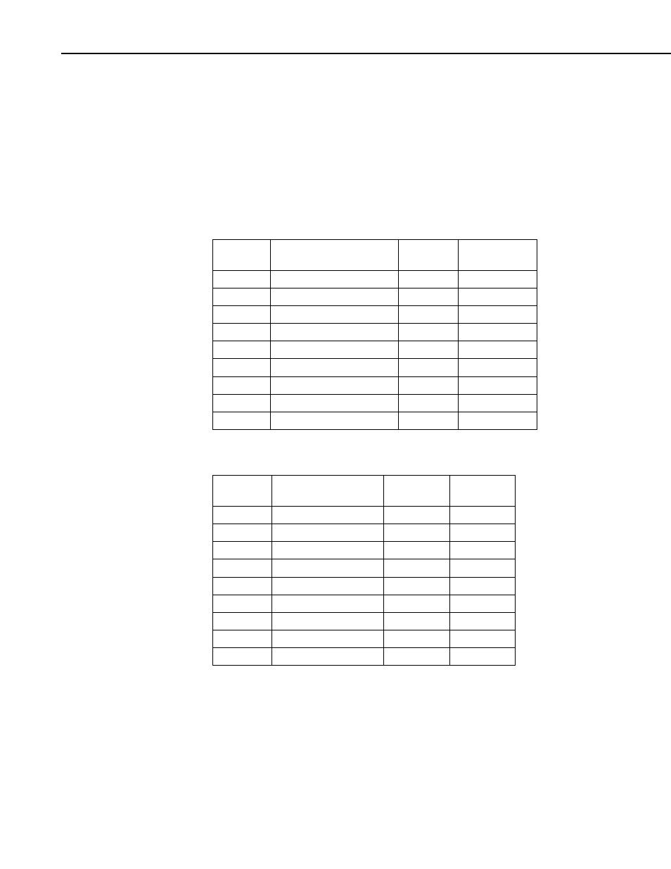
see Appendix A. Table 4-2 provides the electrical connections of the NR01.
Cable 1 (Solar)
Color
Wire Label
Polarity
PCB04
Connection
Red
Pyranometer Up Sig
+
2
Blue
Pyranometer Up Ref
-
1
White
Pyranometer Down Sig
+
8
Green
Pyranometer Down Ref
-
7
Brown
Pyrgeometer Up Sig
+
4
Yellow
Pyrgeometer Up Ref
-
3
Purple
Pyrgeometer Down Sig
+
6
Grey
Pyrgeometer Down Ref
-
5
Clear
Shield
Ground
11, 12
Cable 2 (Temperature/Heater)
Color
Wire Label
Polarity
PCB05
Connection
Red
Current Excite
+
2
Blue
Current Return
-
4
White
PT100 Signal
+
3
Green
PT100 Signal Ref
-
5
Brown
Heater Power SW12V +
1
Yellow
Heater Ground
-
6
Purple
Ground
GND
7
Grey
Shield
GND
8
Clear
Shield
Ground
9, 10
NOTES:
(1) + connections of radiometers give + signal when radiation comes in.
(2) Pt100 red and white end at same side of the sensor (both +)
(3) Pt100 and heater polarity are not critical.
16