Duro-t, Chuck dimensions duro-t, Technical data – ROHM DURO-T hand-operated chuck (with key bar principle) User Manual
Page 39: Technical data - key bar chucks, Key bar c huc ks duro-t
39
3012
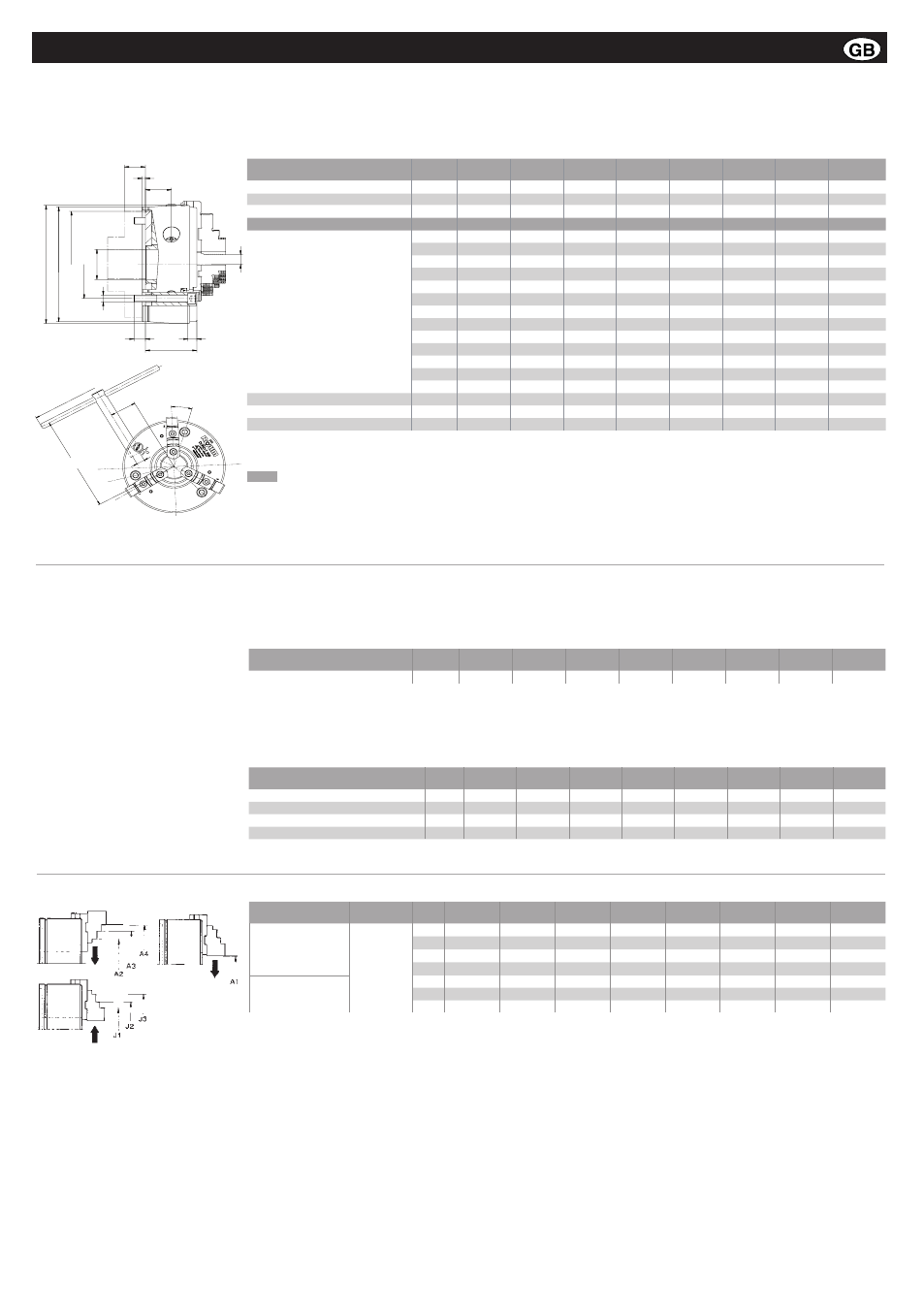
Chuck dimensions DURO-T
Technical data - Key bar chucks
A
A1
E
B
C
G
H
J
D
P
F
Q
K
Chuck size A
125
160
200
250
315
400
500
630
Outer-
ø
A1
128
164
206
256
322
407
507
630
Jaw movement
B
4,8
6,2
6,8
8
10,2
12,5
12,5
14
Bore
C
32
42
52
62
87
102
162
252
Bore cab be enlarged
C max.
35
45
55
75
102
130
180
270
D
46,5
63
81
92
111
118
118
143
EH6
115
145
185
235
300
380
460
580
F
4
5
5
6
6
6
6
6
G
100
125
160
200
250
315
400
520
H
3xM8
3xM10
3xM12
3xM16
3xM20
3xM24
3xM24
3xM24
J
12
15
18
25
30
37
37
37
K
22,5
31,5
43
47
59
57,7
57,5
72
L
32,5
42
53,5
66,5
86
110
152,5
196
M
SW8
SW10
SW12
SW14
SW17
SW19
SW19
SW24
N
117
182
211
284
309
359
356
570
O
180
210
270
450
500
600
600
600
P
8,5
13
14
17
21
25
25
29
Min. thickness of flange
Q
17
30
30
35
35
40
45
55
Moment of inertia GD2 1)
kgm
2
-
0,13
0,41
1,14
3,25
8,8
22
70
α
21
o
35´
22
o
18
o
19
o
17
o
20
o
15
o
69
o
30´
approx. kg
kg
4,0
9,3
18,6
34,5
64
112
166
300
1) The moment of inertia was measured with base jaws but without top jaws or back plate
The bore could be enlarged (measure C, at surcharge)
Enlarged bore max.
Chuck size
125
160
200
250
315
400
500
630
Max. speed
min
-1
6000
5400
4600
4200
3300
2200
1900
1100
Max. permissible speed
The maximum permissible speed has been fixed so that 1/3 of the gripping force is still available as residual gripping force if
the maximum grippping is applied and the chuck is fitted with its heaviest jaws. The jaws may not project beyond the outside
diameter of the chuck. The chuck must be in perfect condition. The specification DIN 6386 Part 1 shall be observed.
Gripping force
The gripping force is the sum total of all jaw forces acting radially on the stationary workpiece.
The specified gripping forces are standard values.
They apply to chucks in a perfect condition which have been lubricated with RÖHM grease F79 and F80.
Chuck size
125
160
200
250
315
400
500
630
Torque applied on key
1)
Nm
20
40
60
70
80
90
100
100
Total gripping force
1)
kN
8,5
30
48
66
80
95
102
102
Torque applied on key
Nm
40
120
155
190
210
260
320
350
Max. total gripping force
kN
23
73
114
185
240
260
290
320
1) Maintaining the accuracy
Chuck size
125
160
200
250
315
400
500
630
External chucking
Jaw
position
A1
3-30
5-51
7-70
8-97
12-131
16-168
64-256
30-322
A2
31-65
45-91
58-123
82-172
93-216
119-278
167-360
200-490
A3
63-97
89-135
114-179
-
-
-
-
-
A4
95-129
115-161
142-207
163-253
201-323
260-413
308-501
360-650
J1
26-59
67-105
71-131
99-182
102-213
120-272
166-360
184-489
Internal chucking
J2
57-91
93-132
99-159
-
-
-
-
-
J3
89-123
135-174
154-214
178-261
207-319
260-412
306-500
341-646
Chuck capacities of jaw steps
Key bar c
huc
ks DURO-T
O
L
α
N
8. Technical data
Montage- und Betriebsanleitung für
Fremdsprachentexte ...
Handspannfutter (Keilstangenprinzip)
Fremdsprachentexte ...
Fremdsprachentexte ...
mit Backensicherung
DURO-T
E
F
RUSS