Clamping force/speed of rotation diagram, Clamping force/actuating force diagram, 3 permitted speed of rotation – ROHM DURO-NC - Power chucks with quick-acting jaw change system User Manual
Page 14: 2 determining the permitted speed of rotation, Important
7.3 Permitted speed of rotation
The following formula applies for determining the
permitted speed of rotation for a specific machining
job:
n
perm
=
(Nothe the number of jaws for
Σ
M
c.
)
F
spo
-- (F
spz
.
S
z
)
[min
--1
](9)
M
c
30
π
.
n
7.2.1 Centrifugal force F
c
, and centrifugal moment M
c
Formulae (1), (2) and (3) produce the following result for
clamping from the outside in:
F
sp
=
-- F
c
[N]
(4)
In this case the centrifugal force F
c
is dependent on
the mass of all jaws m
B
, the centre of gravity radius r
s
and
the speed of rotation n.
The following formula can be derived:
F
c
= (m
B
.
r
s
)
.
(
) [N]
(5)
The expression m
B
⋅
r
s
is called the centrifugal
moment M
c
M
c
= m
B
.
r
s
[mkg]
(6)
The following formula applies to chucks with sliding and
false jaws in which the false jaws AB can be moved in
order to alter the clamping area and the sliding jaws GB
approximately maintain their radial position:
M
c
= M
cGB
+ M
cAB
[mkg]
(7)
M
cGB can be obtained from the table below.
M
cAB can be calculated using the following formula:
M
cAB
= m
AB
⋅
r
sAB
[mkg]
(8)
The clamping forces can be obtained by referring to the
clamping force/speed of rotation diagram (see page 28)
when using standard series production
jaws allocated to specific chuck by the chuck
manufacturer.
F
spo
S
sp
π
30
Do not exceed the maximum speed of rotation n
max
of the chuck (marked on the body of the chuck).
This applies even if the calculated permitted
speed of rotation n
perm
is greater than the maximum
speed n
max
.
7.2 Determining the permitted speed of rotation
2
at
max
.
s
peed
Ch
u
c
k
8. Clamping force/speed of rotation diagram
see page 33
9. Clamping force/actuating force diagram
see page 34
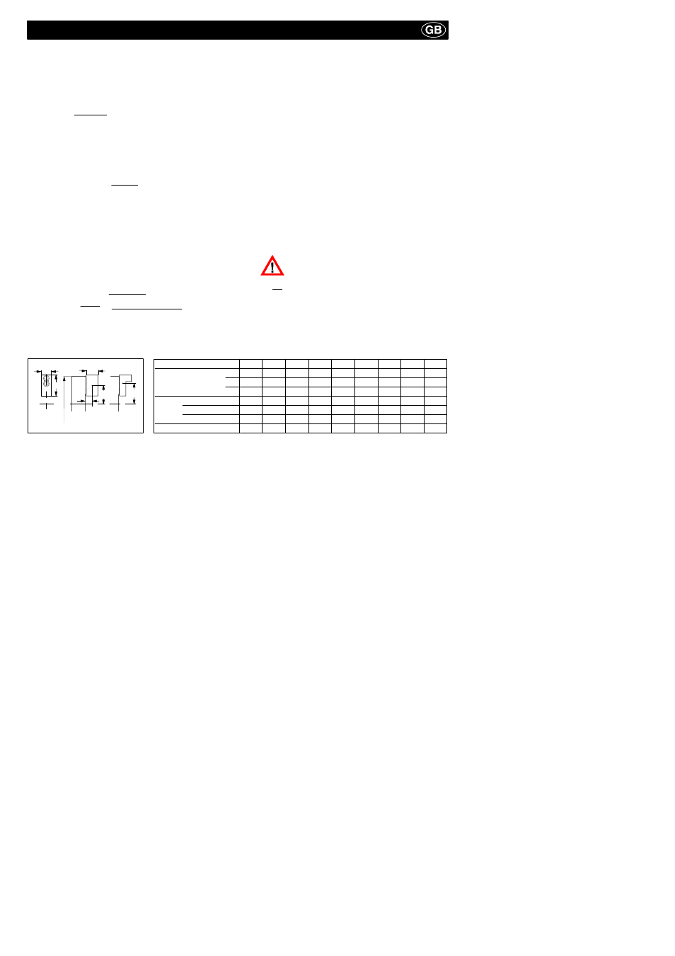
B
A
C
o/
L
A
R
A
r
s
Chuck-size
140
160
175
200
250
315
400
500
630
A
85
85
85
105
125
145
180
180
260
B
20
20
20
22
30
34
50
50
68
C
41
41
41
45
55
56
80
80
110
Max. weight in kg
0,43
0,43
0,43
0,73
1,5
2,27
4,5
4,5
13
R
a
max. in mm
45
55
62
70
93
112
140
190
220
L
a
max. in mm
26
26
26
29
35
36
48
48
62
Centrifugal moment M
c GB
[mkg]
0,0182
0,048
0,0575
0,087
0,194
0,406
0,89
1,36
3,15
Important: