D-m-e company, Refer to mini-print no. 1700, Replacement thermocouple – DME Heaters and Auto-Fixed Integral Heater Distributor Probes User Manual
Page 2: End caps for distributor probes
Please read carefully before installing components.
ME-0725-PS-215-B 09-08 FDP/ID
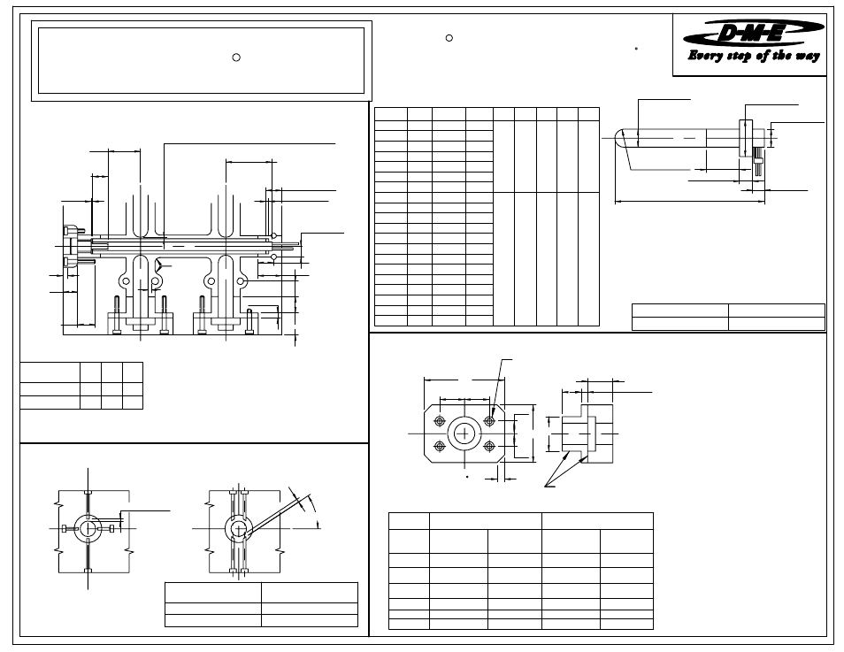
INSTALLATION DATA FOR MICRO SERIES DISTRIBUTOR TUBES,
REFER TO MINI-PRINT NO. 1700
END CAP, HEATERS AND AUTO-FIXED
"INTEGRAL HEATER"
DISTRIBUTOR PROBES, END CAPS.
R
FULL RAD.
B DIA.
±0.002
E
±0.010
0.500
±0.002
C DIA.
-0.002
0.000
D DIA.
-0.005
0.000
0.50
±0.005
L
probe, but in no way alters its
MATERIAL, S-7 STEEL OR EQUIVALENT WITH 32-34 Rc HARDNESS.
AUTO-FIXED "INTEGRAL HEATER" DISTRIBUTOR PROBES
R
(240 VAC, T/C TYPE J, LEADS ARE 34" LONG AND 90 )
REPLACEMENT THERMOCOUPLE
(ALL PROBES)
NOTE: PROBE DISCOLORATION
Each Integral Heater probe sold by
D-M-E is pre-tested. This procedure
discolors the outer surface of the
performance or dimensions.
D
E
D
E
B
A
0.25 x 45 (4)
F
0.25
1.125
C
END CAPS FOR DISTRIBUTOR PROBES
2 PIECE CONSTRUCTION
DRILLED AND
C'BORED FOR
2 PIECE CONSTRUCTION
# 3/8-16 S.H.C.S
# THREAD ENGAGEMENT INTO MOLD MUST BE 1.00 MINIMUM AND TORQUED TO
25-30 FOOT POUNDS.
MATERIAL, AISI 4140 STEEL OR EQUIVALENT WITH 28-35 Rc HARDNESS
0.005 TYP.
45°
0.005 TYP.
RECOMMENDED RELATIONSHIP BETWEEN
NOTE: - S SPLIT LINE OF MOLD
L
SL
DISTRIBUTOR PROBE AND SUPPORT PINS
0.39
0.75
MIN.
1.00
MIN.
SEE
NOTE #2
0.080
±0.010
0.750
1.000
MIN.
0.250
Z
Y
X
0.562
SEE
NOTE #3
0.093
0.25 MAX
2.187 MIN.
2.750 MAX.
SEE NOTE #1
0.093
0.750
MIN.
1.187 MIN.
1.750 MAX.
SEE NOTE #1
0.080 PLUS DISTRIBUTOR PROBE EXPANSION
ON ALL DISTRIBUTOR PROBE INTERSECTIONS
0.250 RAD.
0.250 RAD.
TYP.
TYP.
MICHIGAN 48071 USA
1-800-626-6653
29111 STEPHENSON HIGHWAY
MADISON HEIGHTS
www.dme.net
D-M-E COMPANY
Note: Dimensions shown in Inches.
X
MIN.
Y
MIN.
Z
MIN.
PROBES, INTERSCTIONS AND END CAPS
RECOMMENDED RELATIONSHIP BETWEEN HEATERS,
0.394 DIA.
0.788 0.500 1.375
0.625 DIA.
1.250
between dowel pin and end cap centerlines is recommended
3. The use of (2) 0.250 dia. dowel pins with 0.562 distance
(Solid Block Distributor System only).
to secure end cap into mold
evenly and torqued to 25-30 foot pounds.
Split Plate Distributor System) Screws must be tightened
-mended to secure end caps to mold. (Solid Block and
with 1.00 minimum thread engagement into mold is recom
2. The use of (4) 3/8-16 hardened socket head cap screws
will not be centered in distributor tube.
1. Due to the longer no heat section atthe Lead end, heater
NOTES:
0.875 1.375
FDP0017 8.500
0.009
670
FDP0018 9.000
0.009
705
FDP0019 9.500
0.010
745
FDP0020 10.000
0.010
785
+0.010
2.000
1.98
B
-0.000
+0.010
2.500
2.49
-0.000
+0.010
2.000
1.98
A
MACHINING
0.625 DIA.
PROBE
DISTRIBUTOR
0.625 DIA.
MACHINING
0.394 DIA.
PROBE
DISTRIBUTOR
0.394 DIA.
DIM
ECP0006
ECP0003
CAT. NO.
-
0.875
-
0.500
F
0.375
0.375
0.221
0.625 DIA.
0.139
0.394 DIA.
48"
TC-9900
LEAD LENGTH
CATALOG NUMBER
X
PROBE
DISTRIBUTOR
0.437
0.437
E
0.875
0.875
0.656
0.656
D
-0.000
+0.001
1.125
1.124
-0.000
+0.001
0.875
0.874
C
-0.000
+0.010
2.000
1.98
-0.000
CAT.
NO.
L
EXPAN-
SION
WATTS
A
B
C
D
E
FDP0001 3.500
0.004
175
0.394 0.384 0.740 0.394 0.750
FDP0002 4.000
0.004
200
FDP0003 4.500
0.005
225
FDP0004 5.000
0.005
250
FDP0005 5.500
0.006
275
FDP0006 6.000
0.006
295
FDP0007 6.500
0.007
320
FDP0008 4.000
0.004
315
0.625 0.615 1.240 0.625 1.125
FDP0009 4.500
0.005
355
FDP0010 5.000
0.005
395
FDP0011 5.500
0.006
430
FDP0012 6.000
0.006
470
FDP0013 6.500
0.007
510
FDP0014 7.000
0.007
550
FDP0015 7.500
0.008
590
FDP0016 8.000
0.008
630
DISTRIBUTOR
PROBE