DME Global Thinswitch User Manual
Page 2
2
Limited Warranty
Seller warrants that this product supplied will conform to the description herein stated and that the product will be of standard quality. This is
the sole warranty made by Seller with respect to this product. Seller expressly disclaims any other express or implied warranties, including,
but not limited to, the implied warranty of merchantability and the implied warranty of fitness for a particular purpose.
Seller shall not be liable for any cost or damages, whether direct, incidental or consequential, including, but not limited to, any injury, loss or
damage resulting from the use of this product, regardless of whether any claim for such cost or damages is based on warranty, contract,
negligence, tort or strict liability. The sole liability of Seller is limited to repairing or replacing this product.
This warranty shall not apply to any products that have been repaired or altered by anyone other than Seller. The warranty shall not apply to
any products subject to misuse due to common negligence or accident, nor to any products manufactured by Seller which are not installed or
operated in accordance with the printed instructions of Seller or which have been operated beyond the rated capacity of the goods.
Specifications
Rated current is dependent upon operating temperature. A lower
operating temperature allows more current safely through the
Thinswitch®. See the table below for details.
Above rated current is resistive. Thinswitch is not intended for
inductive load.
Switching Element Contacts
BeCu with Hard Gold Plating .......SPST
Component Materials
Body ................................................Fiberglass-Reinforced Nylon
Spring ..............................................#301 Stainless Steel
Back Cover......................................Polyester Film
Protective Dome..............................Polyurethane
Wire Leads ......................................28ga stranded copper
2 conductor, shielded
cable, 2m long,
ends stripped and tinned
Rated Current (Resistive) vs.
Operating Temperature
mAmps
°C
°F
100
29.4
85
90
49.0
120
80
68.3
155
70
79.4
175
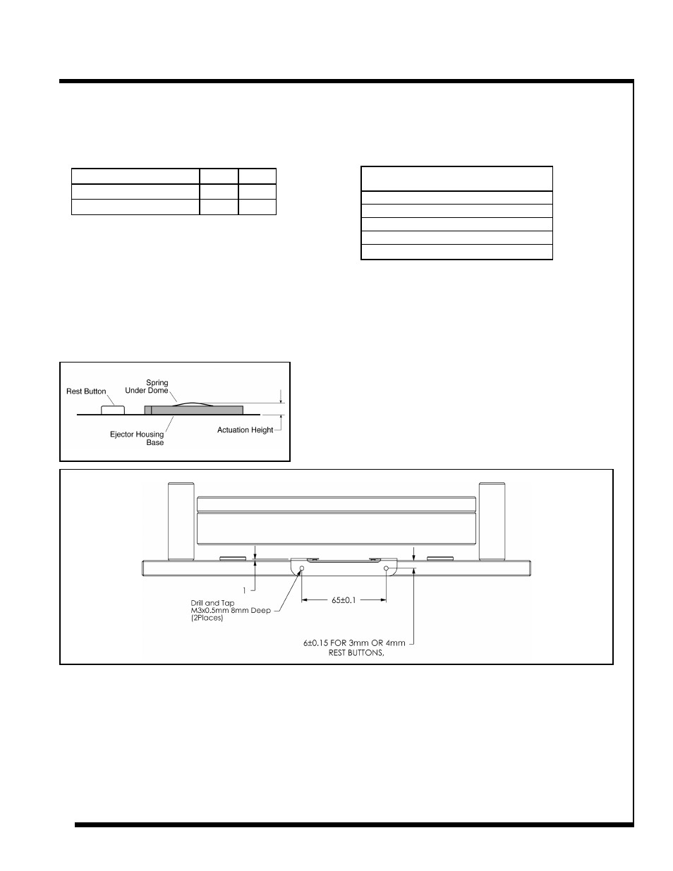
Figure 5
Operation
• The actuation height of the switch is adjusted by
turning the set screw with included hex key (see
Figures 2 and 3).
• Recommended actuation height:
• Each 1/4 turn of the adjusting screw changes
actuation height approximately .14mm.
• Adjust the actuation height to .25mm - .35mm
before the end of the ejector plate stroke.
Premature spring and switch
failure may result by adjusting the
operating point more than .5mm
before the end of the ejector plate
stroke.
Min.
Max.
without 1mm Spacer
3.2mm 4.2mm
with 1mm Spacer
4.2mm 5mm
Figure 4
Global Thinswitch® Installation and Operating Instructions