D-m-e company, Gate-mate nozzle assemblies, Installation data – DME Gate-Mate Nozzle User Manual
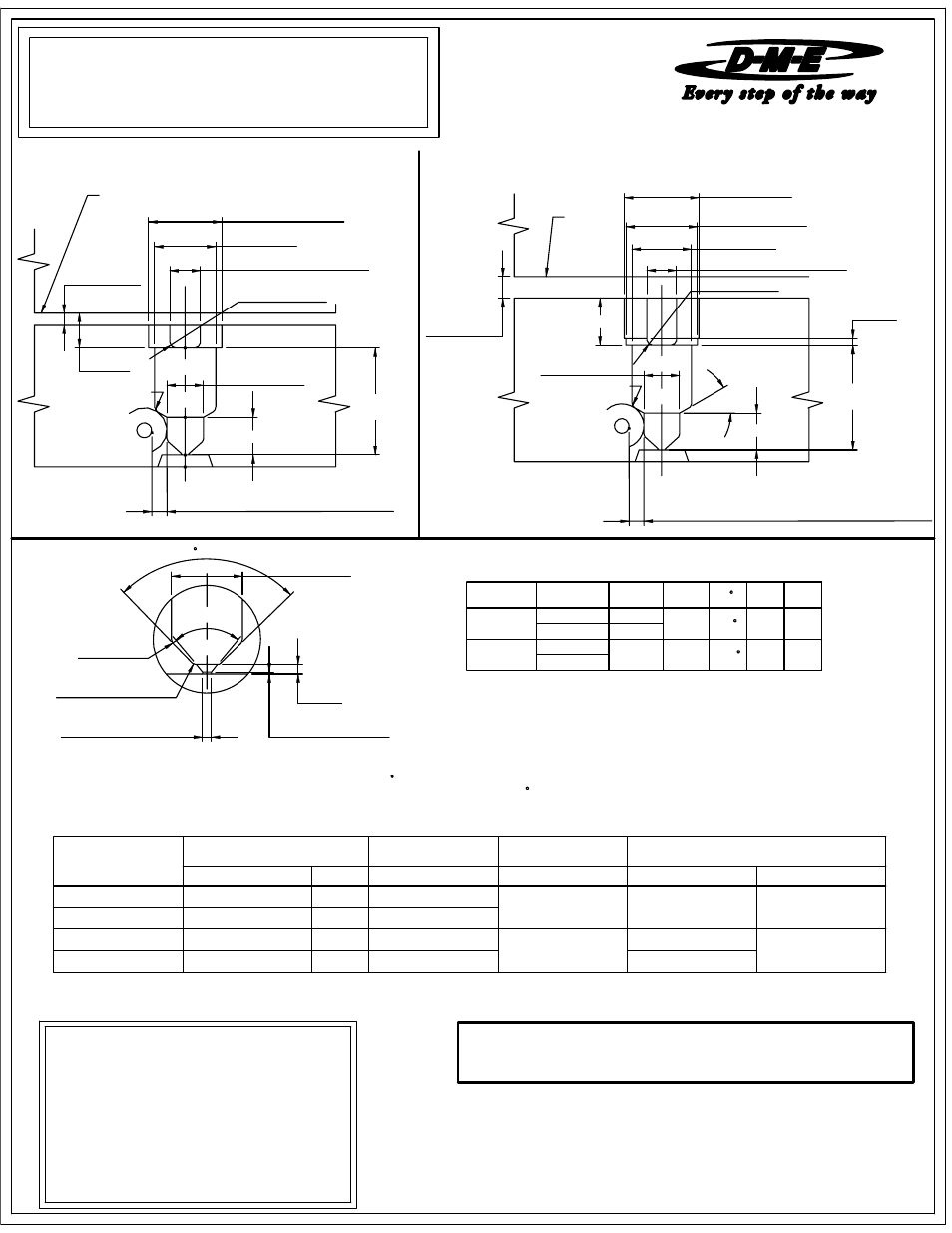
Page 2: Gmb9999, Please read carefully before installing components, Jumbo gate-mate machining dimensions, Mini gate-mate machining dimensions
MICHIGAN 48071 USA
1-800-626-6653
29111 STEPHENSON HIGHWAY
MADISON HEIGHTS
www.dme.net
D-M-E COMPANY
(non-magnetic).
WIRING INFORMATION
Square Coil and cast-In heaters are supplied with
2" prestripped 42" long leads. Heaters are 240 VAC
(120 VAC square coil heaters are available on request).
2 power leads are MULTI COLOR
1 ground lead is GREEN.
Thermocouples are "J" Type.
Thermocouples are supplied with 40" leads.
1 T/C lead is WHITE and negative (-) constantan
1 T/C lead is BLACK and positive (+) iron (magnetic).
J INCL
80°
INCL
B
0.0000
+0.0005
DIA.
K RAD.
0.005 LAND (MAX.)
0.030
TO SUIT
M MIN.
0.187 SPH. RAD.
0.140
1.0625
0.125 RAD.
0.625 WIRE CHANNEL
2.000 DIA.
B
0.0000
+0.0050
2.750 DIA.
2.626
0.000
+0.001
DIA.
1.000
0.31 MIN. DISTANCE BETWEEN WATERLINE
AND DROP
0.250 MIN.
0.750 MAX.
30°
"A" + BE
SEE NOTE
MANIFOLD
LINE
0.125 RAD.
0.125 RAD.
0.625 WIRE CHANNEL
1.250 DIA.
0.7500
0.0000
+0.0005
1.501
0.000
+0.001
DIA.
0.400
0.31 MIN. BETWEEN WATERLINE
AND DROP
0.250 MIN
0.500 MAX.
0.6250
"A" + BE
SEE NOTE
MANIFOLD
0.125 RAD.
LINE
PURPOSE. IN NO EVENT SHALL D-M-E BE RESPONSIBLE FOR LOSS OF USE, REVENUE
D-M-E SHALL NOT BE LIABLE FOR MISUSE OR FAILURE TO FOLLOW THE ENCLOSED
INSTRUCTIONS AND SPECIFICATIONS. D-M-E HERBY TO DISCLAIMS ALL IMPLIED
WARRANTIES, INCLUDING MERCHANTABILITY AND FITNESS FOR A PARTICULAR
OR PROFIT, OR FOR INCIDENTAL OR CONSEQUENTIAL DAMAGED.
Note: Dimensions shown in Inches.
118
90
NOZZLE
EHR0155
TCG0100
225
ME-0739-PS-310-D
GMB9999
factor. In some instances it may be necessary to obtain an empirical factor.
SCH0004
GMB0118
TC-0002
0.125 0.030
GMB0118
then be added to the nominal "A" dimension. Formula for determining this expansion is as follows:
NOTE: The expansion factor must be taken into consideration prior to machining for, and installing nozzle. This factor (BE) must
GMB0120
JUMBO
DIM.
M
1.375
RAD.
BE= 2.500 x 0.00000633 x (500 - 68) = 0.0068.... thus "A" + BE will be 2.5068.
0.375
GMB0110
J
K
0.070
GMB0119
2.500
MINI
JUMBO GATE-MATE MACHINING DIMENSIONS
Please read carefully before installing components.
DIM.
B
DIM.
A
GMT0101
N/A
09-08
225
CAST-IN
0.6250
GMB0110
WEAR RESISTANT #
EXAMPLE: Given a 2.500 Inch "A" dimension, with a nozzle setpoint temperature of 500
F).
Please note that the above information is given as an example. Variations may occur based on mold configuration and cooling
GATE-MATE NOZZLE ASSEMBLIES
STANDARD
GMT0100
STYLE
CATALOG
NUMBER
BE= "A" dimension x 0.0000633 x (nozzle setpoint - 68
F.
MINI GATE-MATE MACHINING DIMENSIONS
INSTALLATION DATA
# # INCLUDES INSTALLATION / REMOVAL WRENCH
# WEAR RESISTANT TIP IS RECOMMENDED FOR ABRASIVE MATERIALS.
3.500
1.2500
SUB-ASSEMBLY
REFERENCE
SQUARE COIL HEATERS
(240 VAC) # #
THERMOCOUPLES
(40" LEADS)
SEAL RINGS
(PKG OF 4)
SUB-ASSEMBLY TIPS
CATALOG NUMBER
WATTS
CATALOG NUMBER
CATALOG NUMBER
CATALOG NUMBER
STYLE
GMB0120
SCH0001
800
TC-0001
EHR0001
GMT0004
GMT0006
GMT0007
STANDARD
WEAR RESISTANT #
THRU HOLE
GMB0119
SCH0002
600