D-m-e company, Refer to : mini print # 1700 – DME Auto-Fixed Integral Heater Micro User Manual
Page 2
PURPOSE. IN NO EVENT SHALL D-M-E BE RESPONSIBLE FOR LOSS OF USE, REVENUE
D-M-E SHALL NOT BE LIABLE FOR MISUSE OR FAILURE TO FOLLOW THE ENCLOSED
INSTRUCTIONS AND SPECIFICATIONS. D-M-E HERBY TO DISCLAIMS ALL IMPLIED
WARRANTIES, INCLUDING MERCHANTABILITY AND FITNESS FOR A PARTICULAR
OR PROFIT, OR FOR INCIDENTAL OR CONSEQUENTIAL DAMAGED.
MADISON HEIGHTS
MICHIGAN 48071 USA
US 800-656-6656
CANADA 800-387-6600
29111 STEPHENSON HIGHWAY
www.dme.net
D-M-E COMPANY
D DIA.
R
45
IN
C
L.
80
SPH.R.
0.030/0.125
0.005 MAX. LAND
0.03
0.25 MIN.
0.625 MIN.
0.625 MIN.
0.630 DIA.
0.395
0.000
+0.001
DIA.
0.25 RAD.
A
0.812 DIA.
0.50 MIN.
(SOLID BLOCK)
0.875/1.125 DIA.
DISTRIBUTOR
BORE
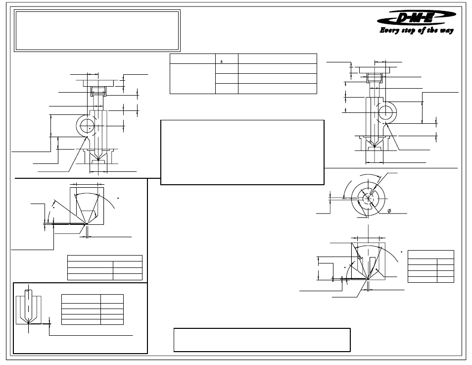
PROBE MACHINING DIMENSIONS - SOLID BLOCK DESIGN
A
0.630 DIA.
0.395
0.000
+0.001
DIA.
0.812 DIA.
0.25 RAD.
0.812 MIN.
0.625 MIN.
0.625 MIN.
0.25 MIN.
(SPLIT PLATE)
0.875/1.125
DISTRIBUTOR
CHANNEL
PROBE MACHINING DIMENSIONS - SPLIT PLATE DESIGN
SL
D DIA.
R
4
5
IN
C
L.
80
SPH.R.
0.005 MAX. LAND
0.03
R0.06
0.378
120.00°
0.06
T DIA.
0.030 / 0.125
Locator, the primary locator must
OPTIONAL LOCATIONS
IMPORTANT: When using a single
be positioned directly opposite the
0.06 R
distributor channel feeding the drop.
AT ROOM TEMPERATURE)
X DIMENSION (PROBE TIP SETTING
further adjustment. Final position of probe tip will be
INITIAL PROBE SET-UP DIMENSIONS
NOTE: X Dimension is for initial probe set up and may require
determined by gate cosmetics and flow requirements.
LINE FOR SPLIT PLATE DESIGNS.
GATE MACHINING DIMENSIONS
(SOLID BLOCK DESIGN)
GATE MACHINING DIMENSIONS
(SPLIT PLATE DESIGN)
REFER TO MINI PRINT 1700
FOR GUIDELINES OTHER THAN THOSE SHOWN
INSTALLATION CHECK LIST
1) Insure that 0.630 diameter counterbore has been machined for probe head.
2) Check the hold down plate thickness and machined channel to
insure contact with probe and fit against adjustment ring.
3) Measure all probe machining dimensions the 0.395 diameter probe bore
must be with in the tolerance specified.
4) Double check that the probe "X" dimension is correct.
NOTE: THE S SYMBOL INDICATES THE SPLIT
L
1 T/C lead is WHITE and negative (-)
0.000-0.003
0.375
(1.125 DIA. CHANNEL OR BORE)
0.010
USED WITH
PROBE
AFIP3 SERIES
AFIP3-360-90
0.000-0.004
AFIP3-410-90
0.000-0.004
AFIP3-460-90
0.812
D DIA.
T DIA.
0.313
iron (magnetic).
1 T/C lead is BLACK and positive (+)
SPH. R.
0.187
R
0.000-0.005
(1.125 DIA. CHANNEL OR BORE)
0.550
0.628 DIA. DISTRIBUTOR TUBE
AFIP3
SERIES
0.428
0.812
constantan (non-magnetic).
09-08
CATALOG NUMBER
X DIM.
AFIP3-310-90
AFIP3 SERIES PROBE
REFER TO : MINI PRINT # 1700
WIRING INFORMATION
SPH. R.
0.187
D DIA.
R
0.375
Please read carefully before installing probes
MICRO PROBES
AUTO-FIXED INTEGRAL HEATER
ME-0725-PS-216-B AFIP/ID
PROBE
Thermocouple is supplied with 48"/ 24 Gage leads.
Thermocouple is "J" Type.
2 power leads are Multi Color.
Heaters are 240 VAC.
Probe Heaters are supplied with 48" long leads.
0.625 DIA. DISTRIBUTOR PROBE
0.544
(0.875 DIA. CHANNEL OR BORE)
0.394 DIA. DISTRIBUTOR PROBE
PROBE
CATALOG NUMBER
A DIMN.