D-m-e company – DME Auto-Fixed Finless Probe User Manual
Page 2
DANGER
WARNING
out residual moisture before applying full power. Failure to do so may cause
IMPORTANT SAFETY INFORMATION
A hot-runner system includes electrical elements and may contain molten
plastic at elevated temperature and pressure. To avoid injury, exercise
caution by reading these instructions before servicing or operating the
system.
These instructions must be passed on to the end user where they should
be read before using this product. Failure to do so can result in serious
injury or death.
Failure to comply can result in serious injury or death:
STORED ENERGY AND HIGH TEMPERATURE HAZARDS
This product maintains molten plastic at high pressure. Use caution when
operating and servicing the system.
Physical contact with molten plastic may result in severe burns. Proper
protective equipment, including eye protection, must be worn. This product
has heated surfaces. Use caution when operating and servicing the system
to avoid severe burns. Proper protective equipment should be worn.
Failure to comply will result in serious injury or death:
ELECTRICAL HAZARDS
Improper voltages or grounding can result in electrical shock. Use only
with proper voltage and a proper earth ground.
To avoid electrical shock, do not operate product when wet.
Do not operate this equipment with covers or panels removed.
To avoid electrical shock, turn off main power disconnect and lockout /
tag out before servicing this device. Do not connect temperature sensors to
electrical power. It will damage the product and it can cause fire, severe
injuries or even death.
If green ground wire present wire must be connected to the ground.
Do not rebend rigid leads. Rebending leads might result in damage to circuit.
Product might absorb moisture when cool. Use low Voltage or power to drive
damage to this product.
MIN.
0.125 R.
(1 1/4"-12 TAP)
1"-8 TAP
(1.125 DIA)
1.000 DIA
DIST. CHANNEL
1.250/2.000 DIA
1.00 MIN
0.875
±0.002
(1.000 DIA)
0.626
0.000
+0.001
(0.751 DIA)
NOT used to establish the location of
Dimensions in parentheses apply to AFPN-720 thru 1020 only
* The purpose of the "B" dimension is to
insure adequate probe bore depth.It is
the distributor tube.
AT RO
O
M
TEM
PERATURE)
X DIMENSION
(P
RO
BE TI
P SETTI
NG
MADISON HEIGHTS
MICHIGAN 48071 USA
US 800-656-6656
CANADA 800-387-6600
29111 STEPHENSON HIGHWAY
www.dme.net
D-M-E COMPANY
A
B
4
5
R
S
P
H
. R.
TO SUIT APPLICATION
GATE DIA. (.040 MIN.)
0.
030
Y
1.
00 MI
N
DIST CHANNEL
1.250/2.000
C
0.
230
±
0
.005
(0.
355)
D DIA
0.62
0.000 - 0.005
AFPN-510
0.000 - 0.004
0.62
1.236
AFPN-1020
AFPN - 720 THRU - 1020
1.125 0.250 0.50
2.12
USED WITH 0.875 DIA.
AFPN-1020
AFPN-410
CAT. NO.
A DIM.
iron (magnetic).
1 T/C lead is BLACK and positive (+)
0.380
DISTRIBUTOR TUBE (1.25 CHANNEL)
PROBE
Thermocouple is "J" Type.
D-M-E
"Refer to chart. Check "X" dimension.
2 power leads are MultiColor.
Heaters are 240 VAC.
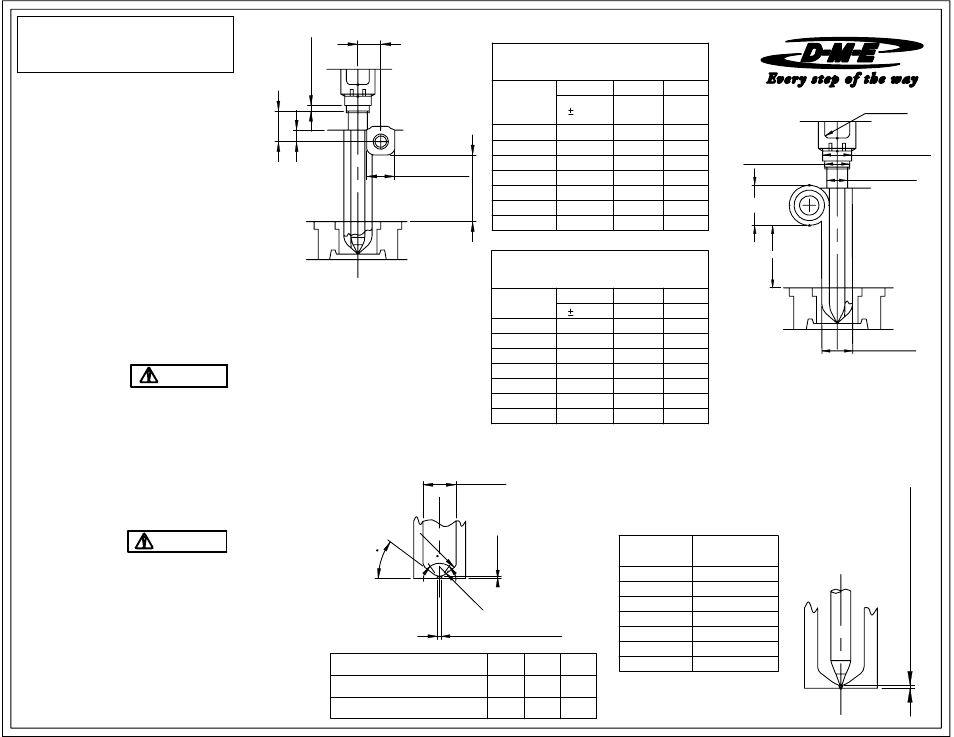
INSTALLATION DATA
AUTO-FIXED FINLESS PROBE
3) Probe Set-Up Dimensions
recommended for the trapezoidal and
Is the "A" dimension within the specified range?
round split plate concept
90° INCL. MAX
INITIAL PROBE SET-UP DIMENSIONS
Y°=80° INCL. MIN
SL
Probe Heaters are supplied with 46'' long leads.
WIRING INFORMATION
PROBE MACHINING DIMENSIONS (NOTE: Dimensions shown are common to either round or trapezoid)
constantan (non-magnetic).
1 T/C lead is WHITE and negative (-)
.
SPH.
2.12
AFPN-820
1.236
0.62
2.12
AFPN-920
1.236
of the probe against the flat surface of the counterbore
Thermocouple is supplied with 46" long leads.
AFPN-610
0.000 - 0.006
AFPN-720
0.000 - 0.007
AFPN-820
0.000 - 0.008
AFPN-920
0.000 - 0.009
AFPN-1020
0.000 - 0.010
AFPN-410
0.796
0.37
1.25
AFPN-510
0.796
0.37
1.25
AFPN-610
0.796
1.96
0.861
0.46
MIN.
MIN.
INSTALLATION CHECKLIST
ME-0725-PS-217-B ID/AFN 08-09
B DIM. * C DIM
0.020
REFER TO MINI-PRINTS 1300, 1400 & 1500
Please read carefully before installing probe
ADJUSTMENT RING
NOTE: ONLY AFPN Series probes are
2) 0.626 (0.751) Diameter Probe Bore
or adjustment ring?
0.62
1.96
0.46
0.861
DIA.
D
1.000
PROBE CAT NO.
X DIM.
CAT. NO.
NOTE: Dimensions are in Inches
PROBE
0.37
Is the thread depth sufficient to permit full tightening
1) 0.875 (1.000) Diameter Counterbore
AFPN - 310 THRU - 610
R
R
1.25
AFPN-720
0.861
0.46
1.96
AFPN-820
0.861
2.12
0.46
1.96
AFPN-920
0.187
USED WITH 1.625 DIA.
DISTRIBUTOR TUBE (2.00 CHANNEL)
PROBE
CAT. NO.
A DIM.
B DIM.
C DIM
0.020
MIN.
MIN.
AFPN-410
1.171
0.48
1.35
AFPN-510
1.171
0.48
1.35
AFPN-610
1.171
0.48
1.35
AFPN-720
1.236