Me-x741-ps-253 - 2, D-m-e company – DME 375 Series Front Load Heater User Manual
Page 2
29111 STEPHENSON HIGHWAY
MADISON HEIGHTS
MICHIGAN 48071 USA
US 800-656-6653
CANADA 800-387-6600
www.dme.net
D-M-E COMPANY
installing and/or removing heater
Please read carefully before
INSTALLATION DATA
375 SERIES FRONT LOAD HEATER
SCH9997 ME-X741-PS-253-E
small gate diameters. High injection rates may require larger gates due to shear heat build up (e.g. high weight thin wall applications). See material manufactures
For selection of tips and gate diameters it is important to take into consideration the materials flow characteristic, shear rate of resin, molding conditions, fill time
requirements, gate vestiage, wall thickness and configuration of part to be molded. Situations requiring high injections velocities must be considered when selecting
literature for further information regarding material to be molded.
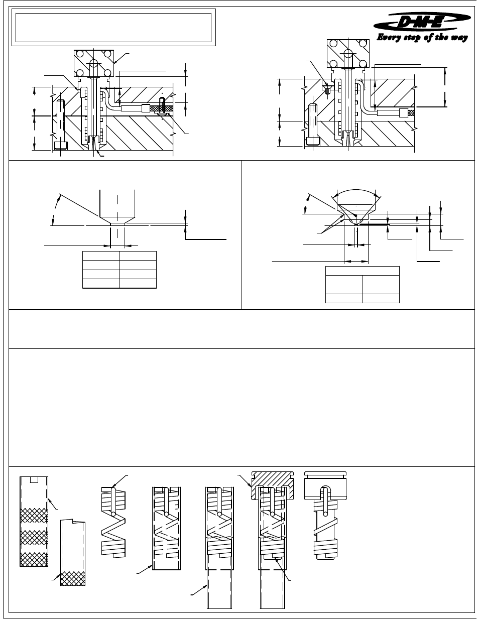
heater can be installed on the nozzle body as follows:
a. Place heater within Tube "A" so that the bending exit lead
1. Front Load Coil Heaters are designed to be used with 375 Series
Nozzles.
2. The nozzle head must be held in such a manner to keep it from
rotating upon installation of the Front Load Heater. This may
be done by making a key for the head to match the flat on the
nozzle's head or by circle interpolation.
3. Nozzle plate must be designed so that the heads of the socket
head cap screws are exposed when the mold is split on the on
the parting line.
4. After the nozzle has been located and positioned in the nozzle
plate with manifold secured in place and "A" plate removed, the
lies within the slot of the tube.
SPRUE AND RING GATE
MACHINING DIMENSIONS
chamfer.
5. The power and thermocouple leads may be spliced in the wiring
channel for ease of heater replacement. Leads may be spliced
using Thomas & Betts nylon insulated disconnects.
Male Cat. No.: 18RA-251T
Female Cat. No.: 18RA-2577
6. Secure wires in wire channel with D-M-E Wire Covers before
b. Insert Tube "B" with angle cut within Tube "A" so that the
angle of the tube mates with the last coil of the heater.
c. Rotate Tube "A" counterclockwise while at the same time rotate
Tube "B" clockwise. This action will spring open the coils
enough to slide the heater onto the shaft of the nozzle body.
d. Slide the heater onto the nozzle body shaft aligning the heater
exit lead within the relief slot in the nozzle's head.
e. Position heater so that the end of the last coil is above the
assembling "A" plate to mold.
TUBE "A"
TUBE "B"
NOZZLE BODY
TUBE "A"
TUBE "B"
LAST COIL TO
BE POSITIONED
ABOVE CHAMFER
FRONT LOAD
HEATER
FRONT LOAD COIL HEATER WRENCH
CAT. NO.: WRE0013
0.875 "B" DIM
1.125
"A" PLT
1.375
NOZZLE PLT
CIRCLE
INTERPOLATION
TUBULAR HEATED
MANIFOLD
DME WIRE
COVER
SPRUE GATE TIP SHOWN
1.875
NOZZLE PLT
"A" PLT
1.375 "B" DIM
1.625
OPTIONAL KEY
MOLDER TO
SUPPLY
30.0°
80.0°
LAND
MAX.
POINT GATE
MACHINING DIMENSIONS
.010-.015 RAD.
UNFILLED
RESIN
AT TANGENT
"O" DIA.
FILLED
.060 MIN.
RESIN
.028 MIN.
30.0°
1.000
1.0005
09-08
RECOMMENDATIONS AND GUIDELINES
.7505
.750
.5005
.500
"S" DIA.
"T" DIA.
WIRING INFORMATION
Square Coil Heaters are supplied with 2"
prestripped 36" long leads.
Heaters are 240 VAC
2 power leads are Multi Color.
1 ground lead is GREEN.
Thermocouple is "J" Type.
Thermocouple is supplied with 36" leads.
1 T/C lead is WHITE and negative (-)
constantan (non-magnetic).
1 T/C lead is BLACK and positive (+)
iron (magnetic).
LAND
+
0.020
R0.187
+
DIA
0.100
0.0005
0.080
0.0000
0.0000 DIA.
0.0005
0.005
"S"
0.5000
0.180
"O" DIA.