Me-0741-ps-554 2, 375 series extended, Sprue gate nozzle – DME 375 Series Extended Sprue Gate Nozzle User Manual
Page 2: Installation data d-m-e company, Important safety information, Esg3/is, Refer to : mini print # 1800
DANGER
WARNING
IMPORTANT SAFETY INFORMATION
A hot-runner system includes electrical elements and may contain molten
plastic at elevated temperature and pressure. To avoid injury, exercise
caution by reading these instructions before servicing or operating the
system.
These instructions must be passed on to the end user where they should
be read before using this product. Failure to do so can result in serious
injury or death.
Failure to comply can result in serious injury or death:
STORED ENERGY AND HIGH TEMPERATURE HAZARDS
This product maintains molten plastic at high pressure. Use caution when
operating and servicing the system.
Physical contact with molten plastic may result in severe burns. Proper
protective equipment, including eye protection, must be worn. This product
has heated surfaces. Use caution when operating and servicing the system
to avoid severe burns. Proper protective equipment should be worn.
Failure to comply will result in serious injury or death:
ELECTRICAL HAZARDS
Improper voltages or grounding can result in electrical shock. Use only
with proper voltage and a proper earth ground.
To avoid electrical shock, do not operate product when wet.
Do not operate this equipment with covers or panels removed.
To avoid electrical shock, turn off main power disconnect and lockout /
tag out before servicing this device. Do not connect temperature sensors to
electrical power. It will damage the product and it can cause fire, severe
injuries or even death.
If green ground wire present wire must be connected to the ground.
Do not rebend rigid leads. Rebending leads might result in damage to circuit.
Product might absorb moisture when cool. Use low Voltage or power to drive
out residual moisture before applying full power. Failure to do so may cause
damage to this product.
D-M-E SHALL NOT BE LIABLE FOR MISUSE OR FAILURE TO FOLLOW THE ENCLOSED
INSTRUCTIONS AND SPECIFICATIONS. D-M-E HERBY TO DISCLAIMS ALL IMPLIED
WARRANTIES, INCLUDING MERCHANTABILITY AND FITNESS FOR A PARTICULAR
PURPOSE. IN NO EVENT SHALL D-M-E BE RESPONSIBLE FOR LOSS OF USE, REVENUE
OR PROFIT, OR FOR INCIDENTAL OR CONSEQUENTIAL DAMAGED.
29111 STEPHENSON HIGHWAY
MADISON HEIGHTS
MICHIGAN 48071 USA
US 800-656-6656
CANADA 800-387-6600
www.dme.net
Controller equipped with Step Smart ® , Smart Step ®
Make sure you maintain this start-up setting for 15 minutes.
OPERATING PROCEDURE
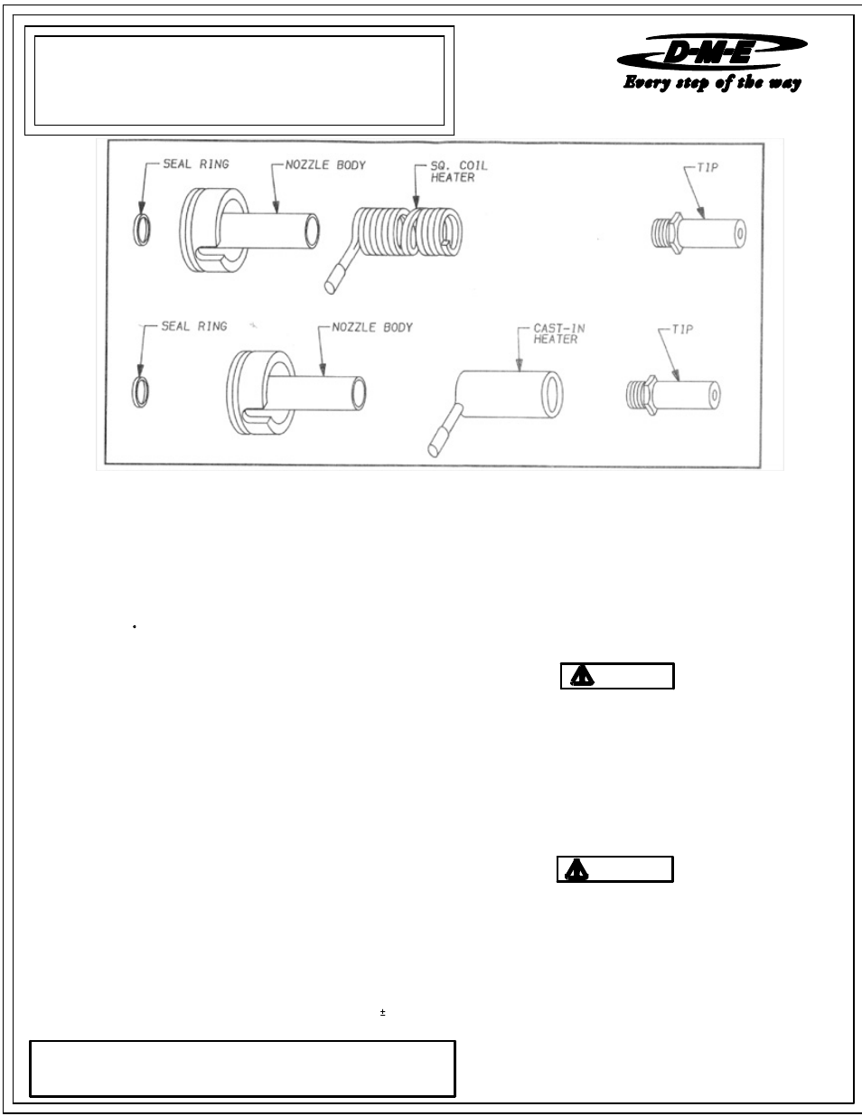
The nozzles are supplied with a Square (Flat) Coil or Cast-In heater equipped with a
Type J Thermocouple.
It is recommended to use a D-M-E closed loop Temperature Controller for optimum
Temperature Control.
375 SERIES EXTENDED
ESG3/IS
heat to transfer into the tip before molding.
8. Wait a minimum of 5 minutes after set point has been achieved for sufficient
When starting the nozzle, set the temperature to 10% voltage if using in open loop
manual type or to 200
procedure will allow the heater to dissipate any moisture.
F if using closed loop automatic type. In either case this
ME-0741-PS-554-D
6. Careful attention should be taken to the heater / thermocouple leads as
REFER TO : MINI PRINT # 1800
08-08
SPRUE GATE NOZZLE
INSTALLATION DATA
D-M-E COMPANY
and the shank. Torque the sub-assembly into the nozzle body using 30
nozzle must be at processing temperature and the heater should be turned off
5 ft-lbs.
the nozzle must be "keyed" to prevent wire damages.
when removing tip counter-clockwise from the nozzle. If nozzle is still in the mold,
3. Tip must be cleaned of any material before reassembling.
damage could occur when working on nozzle assembly.
7. Seal ring for nozzle body must be replaced each time nozzle body and / or
manifold are removed to ensure seal off.
areas before reassembling.
The voltage and wattage of each heater is clearly marked on the heater tag.
2. Install the heater using a Square Coil Heater wrench (Wrench included with
replacement heater). After the heater is installed, it should cover the entire length
of DME Company.
of the nozzle body - stretch the heater by hand if necessary.
ASSEMBLY PROCEDURE
Step Smart ®, Smart Start ® and DME ® are all registered trademarks
or other heater warm-up circuitry will change automatically.
3. Apply an anti-seize compound on the tip threads.
4. Firmly screw the tip sub-assembly into the shank of the nozzle body. Tighten and
1. Nozzle body must be cleaned of any material in the seal off area and threaded
untighten two or three times making sure there is a good contact between the tip
heater. Follow assembly procedures for square coil heater.
5. Cast-in heater may be removed if failure occurs and replaced with a square coil
replacement heater).
2. For removal of tip from nozzle, a six point deep well socket is recommended. The
It is essential to use controllers with the proper voltage and wattage capabilities.
1. Place the nozzle in a vice using "V" Block, then secure it firmly at the nozzle head.
DISASSEMBLY PROCEDURE
4. Remove the heater using a Square Coil Heater wrench (Wrench is included with
For protection of the tip sub-assembly, a six point deep well socket is recommended.
OPERATING & SERVICING INSTRUCTIONS
FOR 375 SERIES EXTENDED SPRUE GATE NOZZLES
All interchangeable nozzles are similar, and differ only in size and material flow
capacity. The information found below applies to the 375 Series Extended sprue
gate nozzles.