21 pin-out reference, 1 connector arrangement, 3 monitor output (bnc) – Videoswitch VK-2 User Manual
Page 81: Vk-2 universal keyboard
VK-2 Universal Keyboard
VK-2 Universal Keyboard User Manual
78
21 Pin-Out
Reference
21.1 Connector
Arrangement
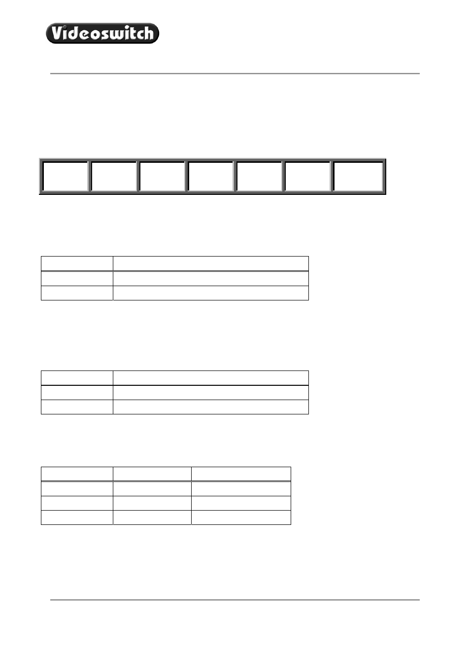
Viewing the VK-2 from the rear, the connectors are arranged in this order:
12V Power
Input
Monitor
Output
RS232
Input
DOMES-2
Output
DOMES-1
Output
VK Input
VK Output
21.2 12V DC Power Input (2.1mm Inlet)
With a CAT5 connection to a Videoswitch Digital Recorder, this power input is not required (for cables runs
up to about 200 metres).
Pin Description
Inner Pin
+12V DC (Range: 9V to 15V), 200mA maximum
Outer Sheath
GND
21.3 Monitor
Output
(BNC)
With a CAT5 connection to a Videoswitch Digital Recorder, with a cable length up to about 200metres, a
monitor may be connected to this BNC connector. For longer runs, a separate coax cable may be required
for the monitor.
Pin Description
Inner Pin
Composite Video (PAL)
Chassis GND
21.4 RS232 (9-way female D-type, DCE)
The RS232 input is provided for firmware upgrade from a PC. Contact Videoswitch for details.
Pin Signal
Name
Usage
2
RXD
RS232 Output
3
TXD
RS232 Input
5 GND
Ground