3 vi405 and vi-r4000 recorders (address range 1), Vi-r4000 series – Videoswitch Vi-R4000 Series User Manual
Page 40
Vi-R4000 Series
Videoswitch Page
34
Mdr602a.doc
3.5.3 Vi405 and Vi-R4000 Recorders (address range 1)
If Vi-R4000 Series Recorders are being cascaded with existing Vi405 DVRs, follow the following
guidelines:
• Make sure the Vi405 DVRs are first in the cascading chain i.e. the including. master unit
• Add Vi-R4000 series units at the end of the chain
• Manually allocate Vi405 and Vi-R4005 addresses in the order the units are physically
connected (see below)
• Manually set each Vi-R40905 address range to 1 (see below)
• Note that Vi405’s do not have VGA or mouse control so cascading of these features is not
possible.
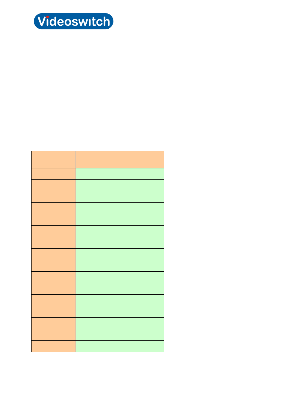
When DVRs each haver and address range of 1 (which Vi405’s always do), the cameras are allocated
as follows:
DVR
Unit Address
Analogue
Cameras
1
1
1 - 16
2
2
17 – 32
3
3
33 – 48
4
4
49 - 64
5
5
65 – 80
6
6
81 – 96
7
7
97 – 112
8
8
113 – 128
9
9
129 - 144
10
10
145 – 160
11
11
161 – 176
12
12
177 – 192
13
13
193 – 208
14
14
209 – 224
15
15
225 – 240
16
16
241 - 256