0 front panel description, 0 parameter mode, Pass – Red Lion TLA User Manual
Page 6: Al-1, Al-2, Cnfp
6
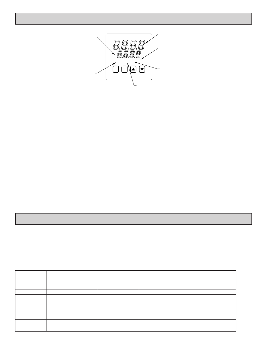
3.0 FRONT PANEL DESCRIPTION
EX OUT A1 A2
P
R
ILLUMINATES WHEN THE LIMIT OUTPUT IS DE-ENERGIZED.
ILLUMINATES WHEN ALARM 2 IS ON.
ILLUMINATES WHEN THE
PROCESS TEMPERATURE
EXCEEDS THE LIMIT
SECONDARY DISPLAY-
DISPLAYS THE LIMIT SETPOINT.
ALSO DISPLAYS MNEMONIC OR
NUMERIC VALUE WHEN
MAIN DISPLAY-
DISPLAYS THE PROCESS TEMPERATURE.
ALSO DISPLAYS MNEMONIC OF SELECTED
PARAMETER IN A CONFIGURATION MODULE.
MODIFYING A PARAMETER.
SETPOINT.
ILLUMINATES WHEN ALARM 1 IS ON.
The front panel bezel material is flame and scratch resistant, tinted plastic that
meets NEMA 4X/IP65 requirements, when properly installed. Continuous
exposure to direct sunlight may accelerate the aging process of the bezel. The
bezel should be cleaned only with a soft cloth and neutral soap product. Do NOT
use solvents. There are two 4-digit LED displays, a red upper Main Display and
a lower green Secondary Display.
There are up to four panel annunciators, with red backlighting, that illuminate
to inform the operator of the TLA and output status. See the front panel diagram
for a description of the annunciators. Four front panel buttons are used to access
different modes and parameters. The following is a description of each button.
Do NOT use tools of any kind (screwdrivers, pens, pencils, etc) to operate the
keypad of this unit.
Button Functions
R - The Reset (R) button is used to reset the limit and alarm relays. The limit output
cannot be reset until the process temperature returns to the proper operating
range. Latched alarms can be reset regardless of limit exceed condition.
P - The Parameter (P) button is used to access programming, enter the change,
and scroll through the available parameters in any mode.
UP, DN - The Up/Down buttons are used to modify parameters.
TLA POWER-UP
Upon applying power, the TLA delays input indication and control action for
five seconds to perform several self-diagnostic tests and to display basic TLA
information. Initially, the TLA illuminates both displays and all annunciators to
verify that all display elements are functioning. The TLA then displays the
programmed input sensor type in the main (top) display and the revision number
of the TLA’s operating system in the secondary (bottom) display. The TLA
checks for correct internal operation and displays an error message (E-xx) if an
internal fault is detected. (See the Troubleshooting section for further
information.)
Upon completion of this sequence, the TLA begins displaying the input value
and setpoint, and updates the outputs based upon this condition.
TLA CONFIGURATION OVERVIEW
The TLA is programmed with certain parameter settings from the factory.
Factory settings are listed in parentheses in the various Configuration of
Parameters tables. In many cases, these settings must be changed to the
particulars of the application before proper operation can be started.
The TLA is typically in the Normal Display Mode. In this mode, the process
temperature is displayed in the main (top) display, and the limit setpoint is
displayed in the secondary (bottom) display. When changes to the parameter
configurations are needed, the P button is pressed, and the TLA will enter into
the Parameter Mode.
PARAMETER CONFIGURATION BASIC STARTUP
For basic start-up, it is important to verify or change Input Parameter Module
(1-IN) parameters tYPE and SCAL, and Output Parameter Module (2-OP)
parameter LiAC (Limit Trip Action). For alarm set-up, it is important to verify
or change Alarms Parameter Module (4-AL) parameters ACt1, AL-1, ACt2, and
AL-2.
If the above Input parameters or the input wiring connections are not correct,
then the main (top) display may display an error message or incorrect value.
Verify the input programming and wiring. (If incorrect display continues, refer
to the Troubleshooting section.) All other parameter configurations are important
but will not prevent the TLA from showing a correct display.
4.0 PARAMETER MODE
The Parameter Mode is accessed by pressing the P Button from the
Normal Display Mode. While in the Parameter Mode, the temperature is
displayed in the main (top) display, and the parameter is displayed in the
secondary (bottom) display. The correct password must be entered before any
parameters can be accessed. To modify values, use the UP or DOWN button
while the parameter is displayed. Use the P button to accept the new value, and
to scroll through the parameters. The TLA will automatically return to the normal
display mode if no action is taken. The TLA responds to the new values
immediately, but the change is not committed to non-volatile memory until the
TLA is returned to the Normal Display Mode. If power loss occurs before
returning to the normal display mode, the new values must be re-entered.
To gain access to the Configuration Parameter Modules continue to CNFP
and press the UP button. These modules allow access to the fundamental set-up
parameters of the TLA. If the setpoint or alarm values are modified, the CNFP
step will be skipped.
DISPLAY
PARAMETER
RANGE
DESCRIPTION
PASS
Password to access parameters
0 to 250
If an incorrect value is entered, the TLA will display “End”
momentarily, and then return to the normal display mode. The
default password is 10. The wildcard password is 222 (in case the
password is forgotten).
SP
Limit setpoint
-999 to 9999
Range limited by SPLO & SPHI.
AL-1
*
Alarm #1
-999 to 9999
The Alarm parameters can be independently locked out from
appearing. See Configuration Module 3, Parameter Lock-outs.
AL-2
*
Alarm #2
-999 to 9999
CNFP
Configuration parameter modules
“Up” button: enter
configuration modules.
End
End of Parameter Mode
When the parameter list has been scrolled through, the TLA
will display “End” momentarily, and then return to the normal
display mode.
Parameter Mode Reference Table
These modules allow access to the fundamental set-up parameters
of the TLA. The modules are grouped into related
programming steps, such as inputs, outputs, alarms, etc. Upon
completion of each module, the program returns to “CNFP”.
* Model Number Dependent.