Calibration checks, Mv reading check, Rtd ohms reading check – Red Lion TLA User Manual
Page 11: Error flag e-cl, Alarm reset sequence alarm standby delay sequence, Thermocouple cold junction temperature check
11
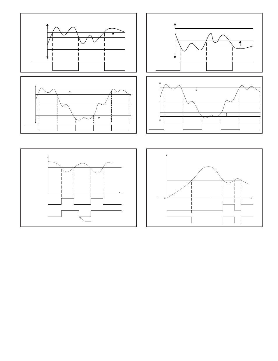
Alarm Reset Sequence
Alarm Standby Delay Sequence
ON
OFF
ALARM VALUE
OFF
ON
OFF
OFF
TIME
AUTOMATIC
RESET
MANUAL
RESET
MANUAL RESET
PERFORMED BY OPERATOR
INPUT
ALARM MODE
(ABSOLUTE LOW ACTING SHOWN)
ON
OFF
ON
OFF
ON
OFF
ON
ON
OFF
ON
OFF
ON
UNIT
POWER-ON
STANDBY
ENABLED
STANDBY
DISABLED
TIME
INPUT
ALARM VALUE
ALARM MODE
(ABSOLUTE LOW ACTING
W/AUTO-RESET SHOWN)
CALIBRATION CHECKS
The instrument has been fully calibrated at the factory for all input types. If
the unit appears to be indicating or controlling incorrectly, see the Troubleshooting
section before attempting this procedure.
If the TLA is suspected of reading incorrectly, the instrument may be checked
for indication accuracy without disturbing the factory calibration. The following
procedures may be used for this purpose.
Note: Allow ½ hour warm-up before checking these parameters.
mV Reading Check
1. Connect a DC mV source with an accuracy of 0.03% or better to terminal #8
(-) & #9 (+).
2. Configure Input Parameters Module 1 for linear mV (Lin) input, under tYPE.
3. Compare the TLA read-out to the standard at various points over the range
(-5.00 mV to 56.00 mV). The tolerance is ±(0.15% of reading + 1 LSD).
4. Calibrate the TLA if the readings are out of tolerance.
Thermocouple Cold Junction Temperature Check
1. Connect a thermocouple probe of known accuracy (Types T, E, J, K, N only)
to TLA. Select the probe used in Configure Module 1.
2. Connect a reference temperature probe to measuring end of thermocouple to
monitor temperature. Allow sufficient time for temperatures to equalize.
3. Compare TLA display with reference temperature probe. The TLA display
should equal the calibrated probe temperature. (Tolerance is ±1ºC.)
4. Calibrate the cold junction temperature if out of tolerance.
RTD Ohms Reading Check
1. Connect RTD simulator (with an accuracy of 0.1 ohm or better) capable of
operating with less than 150 µA to terminals #8, #9, & #10.
2. Configure Input Parameters Module 1 for linear ohms (rLin) input, under tYPE.
3. Compare the TLA read-out with the RTD simulator at various points over the
range 2.0 to 300.0 ohms. The tolerance is ±(0.3% of span + 1 LSD).
4. Calibrate the TLA RTD ohms if out of tolerance.
Error Flag E-CL
If error flag “E-CL” appears at power-up, a loss of calibration parameters due
to noise spikes has occurred. Entering code 77 twice in Factory Service
Operations Module (9-FS) erases the TLA calibration values and defaults the
values to nominal settings. Reading errors of ±10% may result. It is recommended
that the TLA be fully recalibrated. If using thermocouple only, the RTD
calibration need not be performed.
Note: the “E-CL” flag may be cleared by “stepping” through cold junction
calibration procedure without the need to change any calibration values. A
±10% reading error will still exist.
INPUT
DEVIATION LOW-ACTING WITH POSITIVE ALARM VALUE (d-LO)
SP + AL
OUTPUT OFF
LED ON
OUTPUT ON
LED OFF
SP
HYS
OUTPUT ON
LED OFF
OUTPUT OFF
LED ON
SP + (-AL)
DEVIATION LOW-ACTING WITH NEGATIVE ALARM VALUE (d-LO)
INPUT
LED ON
OUTPUT ON
LED OFF
OUTPUT OFF
LED ON
OUTPUT ON
LED OFF
OUTPUT OFF
SP
HYS
OUTPUT ON
LED OFF
OUTPUT OFF
LED ON
OUTPUT ON
LED OFF
INPUT
BAND INSIDE ACTING (b-IN)
SP + AL
OUTPUT OFF
LED ON
OUTPUT ON
LED OFF
OUTPUT OFF
LED ON
SP - AL
SP
HYS
HYS
SP - AL
LED ON
OUTPUT ON
LED OFF
OUTPUT OFF
LED ON
OUTPUT ON
SP + AL
BAND OUTSIDE ACTING (b-Ot)
INPUT
LED OFF
OUTPUT OFF
LED ON
OUTPUT ON
LED OFF
OUTPUT OFF
HYS
HYS
SP