0 installing the tla – Red Lion TLA User Manual
Page 4
The TLA meets NEMA 4X/IP65 requirements for indoor use to provide a
watertight seal in steel panels with a minimum thickness of 0.09 inch, or
aluminum panels with a minimum thickness of 0.12 inch. The units are intended
to be mounted into an enclosed panel. It is designed so that the units can be
stacked horizontally or vertically. The bezel assembly MUST be in place during
installation of the unit.
Instructions:
1. Prepare the panel cutout to the dimensions.
2. Remove the panel latch from the unit. Discard the cardboard sleeve.
3. Carefully remove the center section of the panel gasket and discard. Slide
the panel gasket over the unit from the rear, seating it against the lip at the
front of the case.
4. Insert the unit into the panel cutout. While holding the unit in place, push the
panel latch over the rear of the unit, engaging the tabs of the panel latch in
the farthest forward slot possible.
5. To achieve a proper seal, tighten the
panel latch screws evenly until the
unit is snug in the panel, torquing
the screws to approximately 7 in-lbs
(79 N-cm). Over tightening can
result in distortion of the panel, and
reduce the effectiveness of the seal.
Note: The installation location of the
TLA is important. Be sure to keep it
away from heat sources (ovens,
furnaces, etc.), and away from
direct contact with caustic vapors,
oils, steam, or any other process
byproducts in which exposure may
affect proper operation.
4
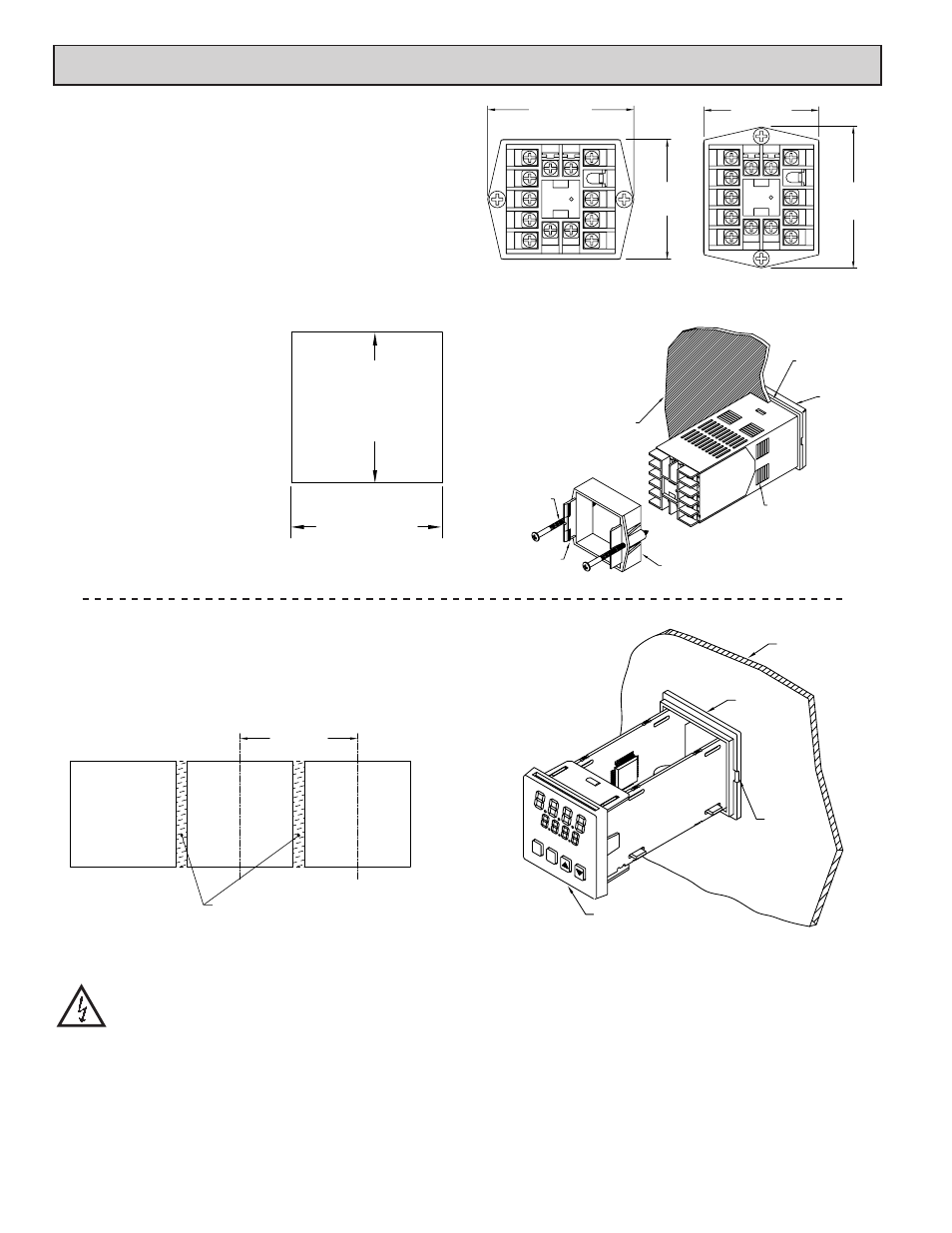
Multiple Unit Stacking
The TLA is designed for close spacing of multiple units. Units can be stacked
either horizontally or vertically. For vertical stacking, install the panel latch with
the screws to the sides of the unit. For horizontal stacking, the panel latch
screws should be at the top and bottom of the unit. The minimum spacing from
center line to center line of units is 1.96" (49.8 mm). This spacing is the same
for vertical or horizontal stacking.
Note: When stacking units, provide adequate panel ventilation to ensure that
the maximum operating temperature range is not exceeded.
Caution: Disconnect power to the unit and to the output control
circuits to eliminate the potential shock hazard when removing the
bezel assembly.
Unit Removal Procedure
To remove a unit from the panel, first loosen the panel latch screws. Insert
flat blade screwdrivers between the latch and the case on either side of the unit,
so that the latches disengage from the grooves in the case. Push the unit through
the panel from the rear.
Removing Bezel Assembly
The bezel assembly must be removed from the case to replace the output
board. To remove the bezel assembly, insert a flat blade screwdriver into the pry
slot on either side of the unit. Twist the screwdriver handle until the unit is
ejected enough to allow removal.
Caution: The bezel assembly contains electronic circuits that can be damaged
by static electricity. Before removing the assembly, discharge static charge on
your body by touching an earth ground point. It is also important that the
bezel assembly be handled only by the bezel itself. Additionally, if it is
necessary to handle a circuit board, be certain that hands are free from dirt,
oil, etc., to avoid circuit contamination that may lead to malfunction. If it
becomes necessary to ship the unit for repairs, place the unit in its case
before shipping.
Installing Bezel Assembly
To install the bezel assembly, insert the assembly into the case until the bezel
is fully seated against the lip of the case. Properly installing the bezel assembly
is necessary for watertight sealing.
1.96 (49.8)
MIN.
IF NEMA 4 IS NOT REQUIRED,
THIS PANEL MATERIAL MAY BE REMOVED.
PANEL
CUT-OUT
STANDARD
PRY
PANEL
SLOT
CASE
LIP
BEZEL
EB0783
R
P
1
2
3
4
5
6
7
8
9
10
13
14
12
11
2.39 (60.7)
MAX.
1.96 (49.8)
MAX.
PANEL LATCH INSTALLED FOR
VERTICAL UNIT STACKING
HORIZONTAL UNIT STACKING
PANEL LATCH INSTALLED FOR
MAX.
2.39 (60.7)
MAX.
1.96 (49.8)
1
2
3
4
5
6
7
8
9
10
13
14
12
11
-0.0
+0.6
-0.000
+0.024
-0.0
+0.6
-0.000
+0.024
(45 )
1.772
(45 )
1.772
LATCHING
BEZEL
LATCHING
PANEL LATCH
PANEL
MOUNTING
SCREW
TABS
SLOTS
PANEL
PANEL GASKET
1.0 INSTALLING THE TLA