General specifications, Input specifications – Red Lion TLA User Manual
Page 2
2
GENERAL SPECIFICATIONS
1. DISPLAY: 2 line by 4-digit LED
Upper (Main) Display: 0.4" (10.2 mm) high red LED
Lower (Secondary) Display: 0.3" (7.6 mm) high green LED
Display Messages:
“OLOL” - Appears when measurement exceeds + sensor range.
“ULUL” - Appears when measurement exceeds - sensor range.
“OPEN” - Appears when open sensor is detected.
“SHrt” - Appears when shorted sensor is detected (RTD only)
“...” - Appears when display values exceed + display range.
“-..” - Appears when display values exceed - display range.
LED Status Annunciators:
EX - Temperature exceeds limit setpoint
OUT - Limit output is de-energized
A1 - Alarm #1 is active
A2 - Alarm #2 is active
2. POWER:
Line Voltage Models: 85 to 250 VAC, 50/60 Hz, 8 VA.
Low Voltage Models:
DC Power: 18 to 36 VDC, 7 W.
AC Power: 24 VAC +/-10%, 50/60 Hz, 9 VA
3. CONTROLS: Four rubber push buttons: R, P, Up, Down
4. MEMORY: Nonvolatile E
2
PROM retains all programmable parameters and
values.
5. ENVIRONMENTAL CONDITIONS:
Operating Range: FM rated @ 0 to 65°C, UL rated @ 0 to 55°C
Storage Range: -40 to 80°C
Operating and Storage Humidity: 85% max. relative humidity (non-
condensing) from 0°C to 65°C.
Vibration to IEC 68-2-6: Operational 5 to 150 Hz, 2 g.
Shock to IEC 68-2-27: Operational 20 g (10 g relay).
Altitude: Up to 2000 meters
6. ISOLATION BREAKDOWN RATINGS:
AC line with respect to all inputs and outputs: 2300 V for 1 minute (250
V working)
Relay contacts to all other inputs and outputs: 2300 VAC
DC Power with respect to sensor input: 50 V working (500 V for 1 minute)
7. CERTIFICATIONS AND COMPLIANCES:
CE Approved
EN 61326-1 Immunity to Industrial Locations
Emission CISPR 11 Class A
IEC/EN 61010-1
RoHS Compliant
Factory Mutual (FM) Listed: File #3014646
UL Recognized Component: File #E156876
Type 4X Enclosure rating (Face only)
IP65 Enclosure rating (Face only)
IP20 Enclosure rating (Rear of unit)
Refer to EMC Installation Guidelines section of the bulletin for additional
information.
8. CONNECTION: Wire clamping screw terminals
Wire Gage Capacity: Two 14 AWG (2.55 mm), four 18 AWG (1.02 mm), or
four 20 AWG (0.61 mm).
Terminal Torque: 1.0Nm (8.9 in-lbs.).
1.4Nm (12.4 in-lbs.) max.
9. CONSTRUCTION: Black plastic alloy case and collar style panel latch.
Panel latch can be installed for vertical or horizontal instrument stacking.
One piece tinted plastic bezel. Bezel assembly with circuit boards can be
removed from the case to change the output board without removing the case
from the panel or disconnecting wiring. Unit meets NEMA 4X/IP65
requirements for indoor use, when properly installed. Flame resistant.
Installation Category II, Pollution Degree 2.
10. WEIGHT: 0.38 lbs (0.17 kgs)
INPUT SPECIFICATIONS
1. SENSOR INPUT:
Sample Period: 100 msec
Step Response Time: Less than 300 msec typ., 400 msec max. (to within
99% of final value)
Normal Mode Rejection: Greater than 40 dB @ 50/60 Hz
Common Mode Rejection: Greater than 120 dB, DC to 60 Hz
Overvoltage Protection: Input overload 120 VAC for 15 seconds max.
2. Failed Sensor Response:
Main Output: Sensor failure will initiate a process shutdown
Display: “OPEN”
Alarms: Upscale
3. INDICATION ACCURACY: ±(0.3% of Span +1°C) at 23°C ambient after
20 minute warm-up. (Includes NIST conformity, cold junction effect, A/D
conversion errors and linearization conformity.
Span Drift (maximum): 130 PPM/°C
4. RTD INPUT: 2 or 3 wire, 100 Ω platinum, alpha = 0.00385 (DIN 43760),
alpha = 0.0039162
Excitation: 150 µA typical
Resolution: 1 or 0.1 degree
Lead Resistance: 15 Ω max. per input lead
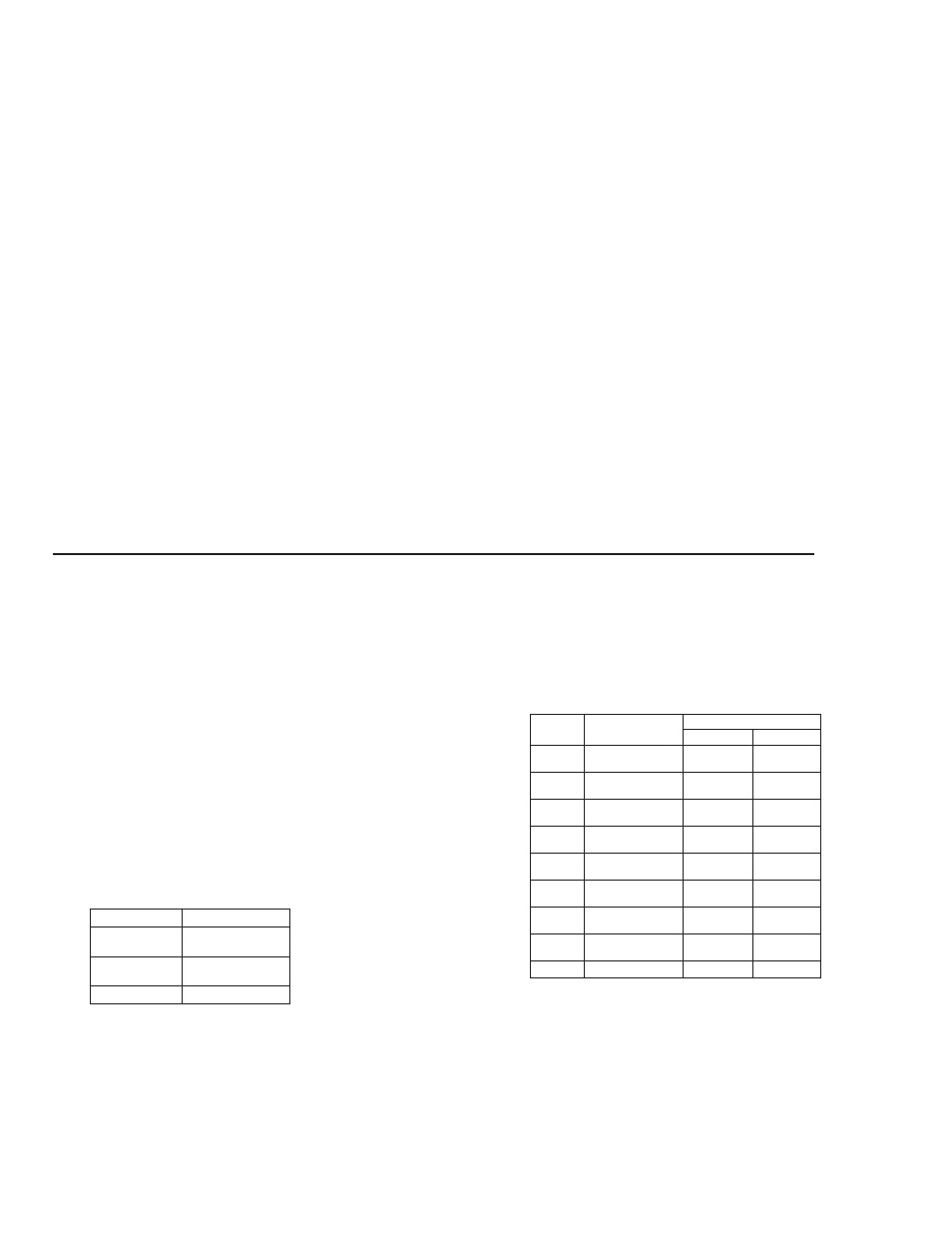
5. THERMOCOUPLE INPUT:
Types: T, E, J, K, R, S, B, N, Linear mV, software selectable
Input Impedance: 20 MΩ all types
Lead resistance effect: 0.25 µV/Ω
Cold junction compensation: Less than ±1°C typ., (±1.5°C max), error over
0 to 65°C max. ambient temperature range. Defeated for Linear mV
indication mode.
Resolution: 1° for all types, or 0.1° for T, E, J, K, and N onlY.
6. REMOTE RESET INPUT: Internally pulled up to +5 VDC (1MΩ).
V
IL
: 0.85 V max., V
IH
: 3.65 V min., V
IN
MAX: 5.25 VDC, I
OFF
: 1µA max.
no standard
no standard
-5.00 to +56.00
orange (+)
blue (-)
orange (+)
red (-)
-200 to +1300°C
-328 to +2372°F
N
no standard
grey (+)
red (-)
+149 to +1820°C
+300 to +3308°F
B
white (+)
blue (-)
black (+)
red (-)
0 to 1768°C
+32 to 3214°F
S
white (+)
blue (-)
black (+)
red (-)
0 to 1768°C
+32 to +3214°F
R
brown (+)
blue (-)
yellow (+)
red (-)
-200 to +1250°C
-328 to +2282°F
K
yellow (+)
blue (-)
white (+)
red (-)
-200 to +760°C
-328 to 1400°F
J
brown (+)
blue (-)
violet (+)
red (-)
-200 to +750°C
-328 to +1382°F
E
white (+)
blue (-)
blue (+)
red (-)
-200 to +400°C
-328 to +752°F
T
BS 1843
ANSI
WIRE COLOR
mV
RANGE
TC TYPE
RTD TYPE
RANGE
385
-200 to +600°C
-328 to +1100°F
392
-200 to +600°C
-328 to +1100°F
OHMS
2.0 to 320.0