0 wiring the tla – Red Lion TLA User Manual
Page 5
5
2.0 WIRING THE TLA
After the unit has been mechanically mounted, it is ready to be wired. All
wiring connections are made to the rear screw terminals. When wiring the unit,
use the numbers on the label and those embossed on the back of the case, to
identify the position number with the proper function.
All conductors should meet voltage and current ratings for each terminal.
Also cabling should conform to appropriate standards of good installation, local
codes and regulations. It is recommended that power supplied to the unit (AC
or DC) be protected by a fuse or circuit breaker. Strip the wire, leaving
approximately 1/4" (6 mm) bare wire exposed (stranded wires should be tinned
with solder). Insert the wire under the clamping washer and tighten the screw
until the wire is clamped tightly.
Caution: Unused terminals are NOT to be used as tie points. Damage to the TLA
may result if these terminals are used.
POWER WIRING
AC Power
Primary AC power is connected to terminals #11 and #12, labeled AC. To
reduce the chance of noise spikes entering the AC line and affecting the TLA,
an AC feed separate from that of the load should be used to power the TLA. Be
certain that the AC power to the TLA is relatively “clean” and within the
variation limit. Connecting power from heavily loaded circuits or circuits that
also power loads that cycle on and off (contacts, relays, motors, etc.), should be
avoided.
DC Power
DC Power (18 to 36 VDC) is connected to terminals #11 and #12 labeled
DC+ and DC- respectively.
CAUTION: Observe proper polarity when connecting DC voltages.
Damage to the unit may occur if polarity is reversed.
SIGNAL WIRING
Thermocouple
When connecting the thermocouple, be certain that the connections are clean
and tight. If the thermocouple probe cannot be connected directly to the TLA,
thermocouple wire or thermocouple extension-grade wire must be used to
extend the connection points (copper wire does not work). Always refer to the
thermocouple manufacturer’s recommendations for mounting, temperature
range, shielding, etc. For multi-probe temperature averaging applications, two
or more thermocouple probes may be connected to the TLA (always use the
same type). Paralleling a single thermocouple to more than one TLA is not
recommended. Generally, the red wire from the thermocouple is negative and
connected to the TLA’s common.
RTD
When connecting the RTD, be certain that the connections are clean and
tight. RTD sensors have a higher degree of accuracy and stability than
thermocouple sensors. Most RTD sensors available are the three wire type. The
third wire is a sense lead for canceling the effects of lead resistance of the probe.
Four wire RTD elements may be used by leaving one of the sense leads
disconnected. Two wire RTD sensors may be used in either of two ways:
A) Attach the RTD to terminals #8 and #10. Install a copper sense wire of the
same wire gauge as the RTD leads. Attach one end of the wire at the probe
and the other end to terminal #9. Complete lead wire compensation is
obtained. This is the preferred method.
B) Attach the RTD to terminals #8 and #10. Install a shorting wire between
terminals #9 and #10. A temperature offset error of 2.5°C/ohm of lead
resistance exists. The error may be compensated by programming a
temperature offset.
Note: With extended cable runs, be sure the lead resistance is less than 15 ohms/
lead.
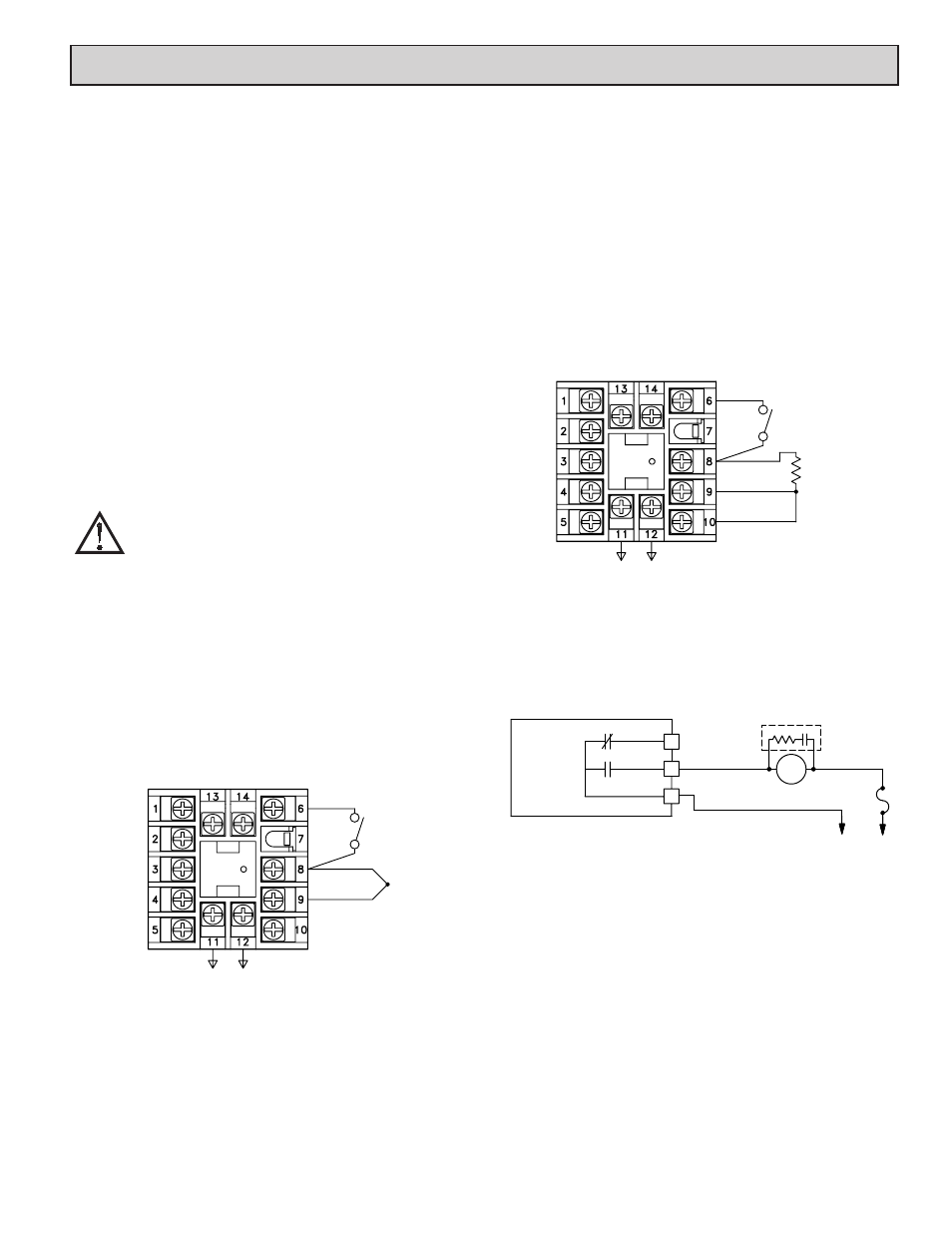
RELAY CONNECTIONS
To prolong contact life and suppress electrical noise interference due to the
switching of inductive loads, it is good installation practice to install a snubber
across the contactor. Follow the manufacturer's instructions for installation.
Note: Snubber leakage current can cause some electromechanical devices to be
held ON.
*Terminal numbers are model dependent. See Terminal Configurations for
description.
REMOTE RESET WIRING
The use of shielded cable is recommended. Follow the EMC installation
guidelines for shield connection.
Terminal #6 is the Remote Reset. Any form of mechanical switch may be
connected to terminal #6 (REMOTE RESET) and terminal #8 (COMM.).
Sinking open collector logic with less than 0.7 V saturation and off-state leakage
current of less than 1 µA may also be used.
POWER
-
+
CONNECTION
NO
TC
COMM.
USER INPUT
AT
5 AMPS
250 VAC
CONTROLLER
N.O.
LOAD
FUSE
N.C.
AC/DC
POWER
*
*
*
Thermocouple Connection
RTD Connection
POWER
COMM.
RTD
USER INPUT
RTD
PROBE