Selection & application of proximity sensors, Dimensions in inches (mm), Maximum sensing distance reduction factors – Red Lion PSAFP - FLAT PACK User Manual
Page 2: Psafp100, Psafp200 mounting, Psafp200
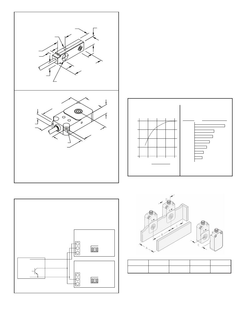
100%
APPROX. 65%
APPROX. 60%
APPROX. 50%
APPROX. 40%
MILD STEEL
STAINLESS
MERCURY
LEAD
BRASS
STEEL
MATERIAL
% SENSING DISTANCE
Nominal sensing range x % sensing
distance = actual sensing range
APPROX. 25%
APPROX. 30%
COPPER
ALUMINUM
0
.25
.5
.75
1
0
50
100
% OF MAX. SENSING DISTANCE
RATIO,
SENSOR DIAMETER
TARGET DIAMETER
1 2 3
SR
C
LO FR
Q
LO BIAS
SN
K
HI
HI
*
*
HI
SN
K
HI
LO BIAS
3
LO FR
Q
SR
C
1 2
APPLICATION
DEPENDENT
APPLICATION
DEPENDENT
TYPICAL COUNTER
INPUT SWITCH SET-UP
INPUT SWITCH SET-UP
TYPICAL COUNTER
NPN OPEN
COLLECTOR
PSAFP1 and PSAFP2
+VDC (BRN)
OUTPUT (BLK)
COMMON (BLU)
COUNTER #2
COUNTER #1
+12V
COMM.
CNT.
CNT.
COMM.
+12V
*
*
SELECTION & APPLICATION OF PROXIMITY
SENSORS
Selection of the proper proximity sensor depends on the size, material, and
spacing of the target being sensed and the sensing distance that can be
maintained. The maximum sensing distance is defined as the distance when the
sensor is just close enough to detect a ferrous target whose diameter is equal to
or greater than the sensor diameter. In actual application, the sensing distance
should be between 50 to 80% of the maximum sensing range to assure reliable
detection. For target sizes smaller than the sensor diameter, the maximum
sensing distance can be estimated from the curve (See Figure 3). A further
reduction factor must also be applied if the target material is non-ferrous metal
(See Figure 4). Ideally, spacing between adjacent targets should be at least one
sensor diameter so that the first target completely leaves the sensors field before
the next target appears. Individual targets can still be resolved as separate
objects if this spacing is reduced to 70 or 75% of the sensor diameter, however,
this can introduce a minimum limit on sensing distance that makes adjustment
more critical. All proximity sensors are internally shielded which allows the
sensor face to be flush mounted in metal applications without reducing sensing
distance. In applications where proximity sensors must be placed next to each
other, a distance of at least 1 sensor diameter should separate sensors to
eliminate any frequency interference (See Mounting below).
PSAFP100 and PSAFP200 outputs are NPN open collector outputs. A
PSAFP100 and PSAFP200 may be used as an input to more than 1
indicator or control only if the respective power supplies of each unit
are “unregulated” and can load share. It is recommended to use only
one power supply for sensor power. An indicator or control with a
regulated power supply may not be paralleled.
MAXIMUM SENSING DISTANCE REDUCTION FACTORS
Reduction in the maximum sensing
distance due to decrease in diameter
of ferrous targets.
Typical reduction factors for various non-
ferrous targets with diameters equal to or
greater than sensor diameter.
Counter #1 and #2 both contain
unregulated +12 VDC Power
Supplies.
Figure 3
Figure 4
DIMENSIONS In inches (mm)
LED
Ш 0.126 (Ш 3.2) THRU
Ш 0.252 (Ш 6.4) x90°
0.315 (8.0)
0.217 (5.5)
0.315 (8.0)
0.630 (16.0)
1.102 (28.0)
0.118 (3.0)
0.236 (6.0)
PSAFP100
Notes:
1. PSAFP100 Housing: Plastic, PA12-GF30
Cable: 2 meter standard length
2. PSAFP200 Housing: Plastic, PBT-GF30-VO
Cable: 2 meter standard length
PSAFP200 MOUNTING
Ш 0.177 (Ш 4.5) 2x
0.787 (20.0)
2.047 (52.0)
1.181 (30.0)
0.551(14.0)
1.260 (32.0)
0.197 (5.0)
0.315 (8.0)
PSAFP200
A
B
C
D
E
30.00 mm
45.00 mm
30.00 mm
30.00 mm
60.00 mm