Psa-6b, 7b, & 8b, Selection & application of proximity sensors, Psa-6b, 7b, & 8b specifications – Red Lion PSA - INDUCTIVE User Manual
Page 2: Dimensions in inches (mm) psa-6b psa-7b psa-8b, Maximum sensing distance reduction factors, Minimum sensor spacing
2
+10 to +30 VDC
@ 10 mA max.
PSA-6B, 7B, & 8B
These Inductive Proximity Sensors have a maximum sensing distance of
0.059" (1.5 mm), 0.197" (5 mm) and 0.394" (10 mm) respectively, and operate
over a wide power supply range (See Specifications Below). They are each
housed in threaded metal cases and are supplied with 2 metal jam nuts for
mounting. The NPN transistor outputs are true open collector and are
compatible with most RLC counter and rate input circuits. Maximum sensing
frequencies are ≤ 3 KHz, 1 KHz, and 500 Hz respectively. In addition, the
outputs are overload and short circuit protected. These sensors are shielded for
flush mounting in metal applications.
PSA-6B, 7B, & 8B SPECIFICATIONS
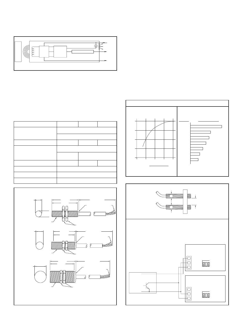
In addition to the coil and oscillator circuit, the 3-wire Models PSA-6B, 7B,
and 8B each contain a Detector Circuit and NPN Transistor Output (See Figure
3). In these units, the Detector Circuit senses when the oscillator stops, and
turns on the Output Transistor which controls the load. The Detector Circuit
also turns on an integrally case mounted L.E.D., visually indicating when a
metal object is sensed.
DIMENSIONS In inches (mm)
PSA-6B
PSA-7B
PSA-8B
NOTES:
1. PSA 6B case material = #303 stainless steel.
2. PSA 7B & 8B case = chromed brass.
3. PVC Cable Jacket.
SELECTION & APPLICATION OF PROXIMITY
SENSORS
Selection of the proper proximity sensor depends on the size, material, and
spacing of the target being sensed and the sensing distance that can be
maintained. The maximum sensing distance is defined as the distance in which
the sensor is just close enough to detect a ferrous target whose diameter is equal
to or greater than the sensor diameter. In actual application, the sensing distance
should be between 50 to 80% of the maximum sensing range to assure reliable
detection. For target sizes smaller than the sensor diameter, the maximum
sensing distance can be estimated from the curve (See Figure 4). A further
reduction factor must also be applied if the target material is non-ferrous metal
(See Figure 5). Ideally, spacing between adjacent targets should be at least one
sensor diameter so that the first target completely leaves the sensors field before
the next target appears. Individual targets can still be resolved as separate
objects if this spacing is reduced to 70 or 75% of the sensor diameter, however,
this can introduce a minimum limit on sensing distance that makes adjustment
more critical. All Proximity sensors are internally shielded which allows the
sensor face to be flush mounted in metal applications without reducing sensing
distance. In applications where proximity sensors must be placed next to each
other, a distance of at least 1 sensor diameter should separate sensors to
eliminate any frequency interference (See Figure 6).
METAL TARGET
CIRCUIT
OSC.
COIL
PSA 6B, 7B, or 8B
+VDC
COMMON
OUTPUT TRANSISTOR
OUTPUT
DETECTOR
LED
Figure 3
LED
.51 (13) ACROSS FLATS
.16 (4) THICKNESS
.315
1.64 (41.6)
6.56' (2 METERS)
#24 AWG
3-CONDUCTORS
1.57 (40)
(8)
M8 X 1
(ISO 68 METRIC
STRAIGHT THREADING)
LED
.94 (24) ACROSS FLATS
.16 (4) THICKNESS
.708
2.13 (54)
6.56' (2 METERS)
#20 AWG
3-CONDUCTORS
1.97 (50)
(18)
M18 X 1
(ISO 68 METRIC
STRAIGHT THREADING)
LED
1.42 (36) ACROSS FLATS
.19 (5) THICKNESS
1.181
2.52 (64)
6.56' (2 METERS)
#20 AWG
3-CONDUCTORS
2.37 (60)
(30)
M30 X 1.5
(ISO 68 METRIC
STRAIGHT THREADING)
MAXIMUM SENSING DISTANCE REDUCTION FACTORS
Reduction in the max. sensing distance
due to decrease in diameter of ferrous
targets.
Figure 4
Typical reduction factors for various non-
ferrous targets with diameters equal to or
greater than sensor diameter.
Figure 5
100%
APPROX. 65%
APPROX. 60%
APPROX. 50%
APPROX. 40%
MILD STEEL
STAINLESS
MERCURY
LEAD
BRASS
STEEL
MATERIAL
% SENSING DISTANCE
Nominal sensing range x % sensing
distance = actual sensing range
APPROX. 25%
APPROX. 30%
COPPER
ALUMINUM
0
.25
.5
.75
1
0
50
100
% OF MAX. SENSING DISTANC
E
RATIO,
SENSOR DIAMETER
TARGET DIAMETER
MINIMUM SENSOR SPACING
Figure 6
Note: PSA-6B, 7B, and 8B outputs are NPN open collector outputs. A
PSA-6B, 7B, or 8B may be used as an input to more than 1 indicator or
control only if the respective power supplies of each unit are
“unregulated” and can load share. It is recommended to use only one
power supply for sensor power. An indicator or control with a regulated
power supply may not be paralleled.
Counter #1 and #2 both contain
unregulated +12 VDC Power
Supplies.
D
D
1 x D
1 2 3
SR
C
LO FR
Q
LO BIAS
SN
K
HI
HI
*
*
HI
SN
K
HI
LO BIAS
3
LO FR
Q
SR
C
1 2
* APPLICATION
DEPENDENT
* APPLICATION
DEPENDENT
TYPICAL COUNTER
INPUT SWITCH SET-UP
INPUT SWITCH SET-UP
TYPICAL COUNTER
NPN OPEN
COLLECTOR
PSA 6B, 7B, or 8B
+VDC
OUTPUT
COMMON
COUNTER #2
COUNTER #1
+12V
COMM.
CNT.
CNT.
COMM.
+12V
PSA-6B
PSA-7B
1. Power Supply:
+10 to +30 VDC
@ 10 mA max.
REVERSE POLARITY PROTECTION
≤ 3 KHz
1 KHz
500 Hz
3. Output:
NPN Open Collector Output,
Overload and Short Circuit protected.
V
SAT
= 1.8 V @
200 mA max. load
4. Maximum Sensing Distance:
0.059" (1.5 mm)
0.197" (5 mm) 0.394" (10 mm)
5. Wire Color Code:
Brown = +VDC; Blue = Common; Black = Output
PSA-8B
6. Operating Temperature:
-25°C to +70°C (-13°F to +158°F)
7. Construction:
NEMA 1, 3, 4, 6, 13 and IEC IP 67
2. Maximum Switching Frequency:
V
SAT
= 1.8 V @
150 mA max. load