Model prdc - proximity sensor – Red Lion DC POWERED User Manual
Page 2
2
MODEL PRDC - PROXIMITY SENSOR
The Model PRDC is a compact, DC powered, Proximity (Diffuse) photo-
electric sensor with a 12" maximum detecting distance (as measured with a
90% reflective white test card). This sensor requires no special reflectors or
reflective tapes and the limited 12" sensing range reduces detection of
background reflections. It is ideally suited for detection of transparent or
translucent objects, parts ejected from presses, and rotating targets such as
pulley spokes. A modulated “infrared” LED light beam provides immunity to
ambient light.
In operation, the modulated light beam is reflected by the object to be
detected. Actual sensing range is determined by the surface area and the
amount of reflectivity of the object. This reflected light is sensed by a photo-
transistor, amplified, demodulated and then energizes the outputs.
ALIGNMENT
With the PRDC in its sensing position, apply DC Power and direct the
infrared light beam at the object to be detected. While observing the Signal
Strength LED, adjust the GAIN (sensitivity) potentiometer for the highest LED
pulse rate. Now remove the sensed object. If the LED goes out, no further
adjustment is necessary. If the LED remains lit, the sensor is “seeing” reflected
light from the background. Reduce the GAIN by steps until the sensor “sees”
the object but not the background. Then turn the pot counter clockwise 2 more
full turns. If the background is still being sensed, it will be necessary to reduce
its reflectivity by either moving it back or painting it flat black.
MODELS EMDC & RCDC - OPPOSED BEAM
EMITTER/ RECEIVER SENSOR PAIR
The Models EMDC (Emitter) and the RCDC (Receiver) are compact, DC
powered, Opposed Beam photo-electric sensor pairs with a 10 foot sensing
range. The Emitter contains a high power modulated “infrared” LED. The
Receiver contains a sensitive photo-transistor, amplifier-demodulator and
output transistors. In operation, these outputs will be triggered when the
Receiver detects that an object begins to break the Emitter beam. Due to their
high gain, they are ideally suited for detecting opaque objects in dirty and dusty
areas or when condensation or oil film environments are present. The small
1/8" well defined beam size allows for sensing small parts accurately and
provides repeatable edge sensing of opaque objects to better than 0.01" for
accurate positioning applications. Greater accuracies can be achieved by
aperturing the Emitter, Receiver or both. However, aperturing will result in
reduced sensing distances. While the beam size is small, the Receiver has a
wide field of view which allows easy “line-of-sight” alignment.
ALIGNMENT
Temporarily mount the Emitter-Receiver Pair opposite, and in line-of-sight,
to each other. Apply DC power to both and aim the Emitter at the Receiver.
Move the Receiver up-down-left-right until the Signal Strength LED lights.
Optimum alignment occurs when the Signal Strength LED flashes at the
highest rate obtainable with the GAIN (Sensitivity) potentiometer adjusted to
the lowest setting needed to light the LED. Mount the units in place. Opposed
Beam Pairs should be used at their highest possible gain. Therefore, have the
object to be detected in “sensing position” and adjust the GAIN potentiometer
fully clockwise (maximum gain). If the Signal Strength LED comes on, “burn-
through” is occurring, and will require that the GAIN pot be backed off
(counter clockwise) until the LED goes out and then backed off 2 more full
turns. Note that Opposed Beam Pairs must be aligned properly and mounted
securely. Excessive movement or vibration can cause loss of alignment and
intermittent or false operation.
PRDC
PROXIMITY
SENSING RANGE UP TO 12"
OBJECT
EMDC
EMITTER
SENSING RANGE UP TO 10'
OBJECT
RCDC
RECEIVER
B
A
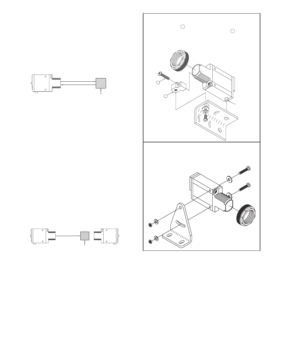
MOUNTING
PEG
MB2 BOTTOM MOUNT BRACKET KIT INSTALLATION
1. Remove lense mounting nut on sensor and bottom lense screw.
2. Align mounting foot A under lense as shown with threaded insert facing
down and attach to lense with long kit supplied screw B .
3. Place sensor mounting peg into bracket hole.
4. Install screw, with washers, into long slotted bracket hole and into
mounting foot threaded insert.
MB3 SIDE MOUNT BRACKET KIT INSTALLATION
1. Remove lense mounting nut from sensor.
2. Install screws with flat washers, through side clearance holes in sen sor
and through top hole and slot of bracket.
3. Install lockwashers and tighten hex nuts.