Red Lion MP-STANDARD MAGNETIC PICKUPS User Manual
Magnetic pickups & in-line preamplifier, Simple, reliable & economical pulse generators for, Description of operation
1
OUTPUT VOLTAG
E
+
-
(A)
SMALL
GEAR
GEAR
OPTIMUM
(B)
GEAR
LARGE
(C)
KEYWAY
SHAFT
(D)
HEAD
BOLT
(E)
CAM
(F)
MAG.
PICKUP
DIA.=d
POLE
d
3d
d
EDGE
LEADING
TRAILING
EDGE
TRAILING
EDGE
LEADING
EDGE
100
75
50
25
0
0
5
10
15
20
25
AIR GAP (INCHES x .001)
REL. OUTPUT
%
SPEED SWITCHES
DIGITAL TACHOMETERS
FREQUENCY TO D.C. CONVERTERS
FEATURES INCLUDE
SELF-GENERATING, NO EXT. POWER NEEDED
WIDE OPERATING TEMPERATURE RANGE
EPOXY ENCAPSULATED, MECHANICALLY RUGGED
IMPERVIOUS TO DIRT, OIL & WATER
NO MAINTENANCE REQUIRED
LOW COST
M12 CONNECTOR (MODEL SPECIFIC)
DESCRIPTION OF OPERATION
A Magnetic Pickup consists of a permanent magnet, a pole-piece, and a
sensing coil all encapsulated in a cylindrical case. An object (target) of iron,
steel, or other magnetic material, passing closely by its pole-piece causes
distortion of the magnetic flux field passing through the sensing coil and pole-
piece, which in turn generates a signal voltage. The magnitude of the signal
voltage depends on the relative size of the magnetic target, its speed of
approach, and how close it approaches. The polarity of the signal depends on
whether the target is moving toward or away from the pole-piece.
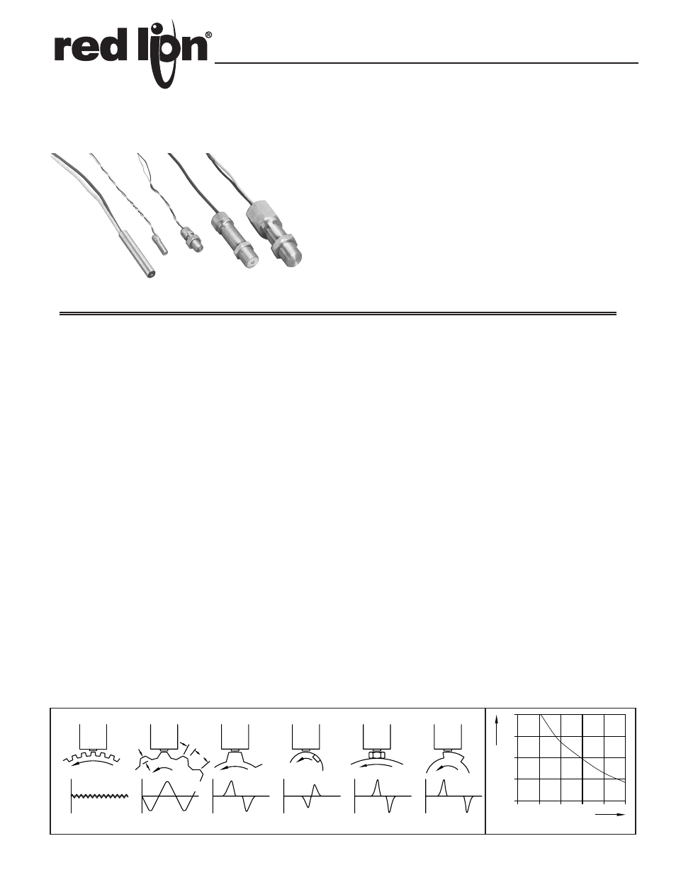
Magnetic Pickups are most frequently used to sense passing teeth on a gear,
sprocket, or timing belt wheel, to bolt-heads, key-ways, or other moving
machine mounted targets. Typical targets and resulting signal wave forms are
shown below in Fig. 1.
SELECTING A MAGNETIC PICKUP
Selecting a magnetic pickup is a matter of matching a pickup to a gear (or
other target), to provide enough input signal to a tachometer, speed-switch, or
other device for operation at the required minimum speed. The open-circuit
output from a magnetic pickup is directly proportional to speed, and once the
minimum operating speed conditions have been met, excess signal will always
be available at higher speeds.
The “1-Volt Threshold Speed” column in the Application and Ordering Table
(next pg.) provides a convenient guide for estimating minimum operating
speeds. This value is the linear surface-speed of a reference gear required to
generate a 1-Volt peak, open-circuit output at an air-gap of 0.005". The
reference gear listed for each pickup is near the optimum size for that pickup,
as defined by the criteria in Fig. 1B. The RPM listed is for a reference gear with
60 teeth running at that surface-speed. Gears with larger teeth provide about the
same or somewhat more output at the same surface-speed, while gears with
smaller teeth or fewer number of teeth yield lower outputs. Figures 1C - 1F need
a very high surface speed to generate a 1-Volt peak. The “Minimum Gear Size”
column lists the Diametral Pitch size at which the output drops to 40-60% of the
output when the reference gear is used. Gears with very small teeth in relation
to the pole-piece diameter, deliver greatly reduced outputs, as shown in Fig. 1A.
Threshold outputs when using targets other than gear teeth can be estimated by
their relative size with respect to the reference gear teeth. For more information
on gears, definitions and relationships, see the Sensing Gears Bulletin.
The 1-Volt Threshold Speeds are based on a 0.005" air-gap. In applications
where this air-gap cannot be maintained or where the air-gap can vary due to
eccentricity of the sensing gear, a correction factor can be applied from the
curve in Fig 2. The effect of electrical loading is usually minimal at low speeds
and low output frequencies, however, output voltage drop due to loading at high
frequency or with low impedance inputs can be estimated based on the Output
Impedance data.
Note: Magnetic Pickups are used primarily for tachometer and other speed
related functions. They are not normally used for counting since loss of
counts will occur at low speeds. Therefore, counters are not designed to
accept outputs directly from conventional magnetic pickups. In special
applications where counting occurs only at running speed or where low-
speed count loss is acceptable, a Model ASTC can be used, or a different type
of sensor can be used as a substitute.
TYPICAL APPLICATION EXAMPLE
A Digital Tachometer, with an input sensitivity of 0.25 V is to be used with a
Magnetic Pickup and gear to indicate speed down to 75 RPM. What are the
alternative choices?
Since the input voltage required by the tachometer is only 0.25 V, the surface
speeds and reference gear RPM’s required would only be 2 of the 1-Volt
Threshold Speeds listed. The MP-25TA with a 60-tooth, 24 D.P. reference gear
would obviously fall short since this combination will not develop 0.25 V until
the reference gear speed reaches 250 RPM.
The MP-37CA with the 60-tooth, 20 D.P. reference gear would both prove
suitable since they would deliver the required 0.25 V at 50 and 45 RPM
respectively. They would also provide some additional margin for air-gap
variation. The curve of Fig. 2 shows a typical output drop of about 25% when
the air-gap is increased from 0.005" to 0.0075". Since the minimum operating
speed in this application is 75 RPM, the additional sensitivity can be traded for
a wider air-gap allowance.
The MP-62TA and MP-75TX with their respective reference gears would
allow operation at even lower speeds. With both of these pickups it would be
possible to drop to a smaller gear pitch for this application.
MAGNETIC PICKUPS & IN-LINE PREAMPLIFIER
SIMPLE, RELIABLE & ECONOMICAL PULSE GENERATORS FOR:
FIG. 1 OUTPUT WAVEFORMS WITH VARIOUS TARGET SHAPES & SIZES
FIG. 2 TYPICAL OUTPUT/AIR-GAP
Bulletin No. MP-L
Drawing No. LP0020
Released 02/10
Tel +1 (717) 767-6511
Fax +1 (717) 764-0839
www.redlion.net