Specifications, Zfh dimensions in inches (mm), Zgh dimensions in inches (mm) – Red Lion ZCH - STANDARD DUTY, QUAD User Manual
Page 2: Ordering information, Length sensor mounting consideration, Equivalent circuit & connections, Electrical specifications, Mechanical specifications
SPECIFICATIONS
ELECTRICAL SPECIFICATIONS
1. SUPPLY VOLTAGE: +8 to +28 VDC (including power supply ripple) @ 50
mA max. (30 mA typ.); Reverse polarity protected.
2. OUTPUTS: NPN Open Collector Transistor, V
OH
= 30 VDC max., V
OL
= 1
V max @ 40 mA. Output current is limited to 40 mA. Incremental - Two
square waves in quadrature with Channel A leading B for clockwise rotation.
3. OUTPUT FREQUENCY: Up to 50 KHz
4. OUTPUT DUTY CYCLE: Channel A & B: 50/50 nominal. (See Figure 1,
Note 3)
5. QUADRATURE OUTPUT PHASE: 90° ±15° (See Figure 1, Note 3)
6. CABLE CONNECTIONS: RED = +VDC; BLACK = Common;
WHITE = Channel A Output; GREEN = Channel B Output.
MECHANICAL SPECIFICATIONS
1. MAXIMUM MECHANICAL SPEED: 6000 RPM
2. RADIAL SHAFT LOAD: 15 lbs. max. (66.7N)
3. AXIAL SHAFT LOAD: 15 lbs. max. (66.7N)
4. STARTING TORQUE: 3 oz.-in. (21.2N-mm)
5. MOMENT OF INERTIA:
Single Shaft = 1.03 x 10
-4
oz. - in. - sec.
2
(7.30 x 10
-4
N - mm - sec
2
)
Dual Shaft = 1.30 x 10
-4
oz. - in. - sec.
2
(9.21 x 10
-4
N - mm - sec
2
)
6. OPERATING TEMPERATURE: 0°C to +70°C
7. WEIGHT (LESS CABLE):
ZCH: 14.3 oz (406 g)
ZFH: 22.0 oz (623 g)
ZGH: 22.7 oz (643 g)
1.65
0.08 (2.03)
0.75
0.04
1.20
MAX.
(30.5)
(41.9)
(1.0)
(19.0)
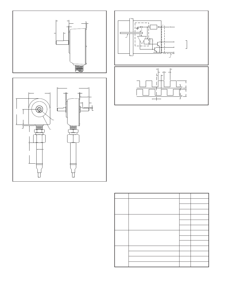
ZFH DIMENSIONS In inches (mm)
.75 (19) DIA.
2.75
(69.8)
2.06
(52.3)
2.00
(50.8)
.13 (3.3)
3.38
(85.8)
2.75 (69.9)
4.00 (101.6)
1.65 (41.9)
0.375 (9.52)
DIA. SHAFT
2.00 (50.8) DIA.
.04
(1.0)
.08
(2.03)
MAX.
USABLE SHAFT
LENGTH
1.08 (27.4)
REF., TYP. 2
.75
(19.0)
TYP. 2
.022 (.56)
TYP. 2
ZGH DIMENSIONS In inches (mm)
This is the side view of the Model
ZFH. All other dimensions (including
the handle tube) are the same as
the Model ZGH. See below.
2
LED
REGU-
LATOR
RED
WHT
BLK
COMMON
8-28VDC @ 30mA
V = 30VDC MAX.
V = 1V MAX. @ 40mA
OL
OH
SHAFT
METAL
ETCHED
OPTICAL
DISC
BARE STRANDED SHIELD WIRE
CONNECTED TO INSTRUMENT
COMMON FOR INCREASED
NOISE IMMUNITY
SENSOR
ARRAY
(TYP.) 50mA MAX.
GRN
CHANNEL A
CHANNEL B
EQUIVALENT CIRCUIT & CONNECTIONS
MODEL NO.
DESCRIPTION
PPR
PART NUMBER
100
100
100
ZGH0100C
ZFH0100C
ZCH0100C
--
200
200
200
ZGH0200C
ZFH0200C
ZCH0200C
500
500
500
ZGH0500C
ZFH0500C
ZCH0500C
ZGH
ZFH
ZCH
Length Sensor
Double Shaft
(Replaces LSQD)
Length Sensor
Single Shaft
(Replaces LSQS)
Rotary Pulse Generator
(Replaces RPGQ)
RPGFC002
--
--
--
Flexible Coupling (1" Length) 0.375" - 6 mm
Flexible Coupling (1" Length) 0.375" - 0.500"
Flexible Coupling (1" Length) 0.375" - 0.375"
RPGFC
RPGFC006
RPGFC004
RPGFC003
Flexible Coupling (1" Length) 0.250" - 0.375"
Note: For 25 foot cable, replace the last character of the part number (“C”) with “D”.
For 50 foot cable, replace the last character of the part number (“C”) with “E”.
ORDERING INFORMATION
NOTES:
1. Channel A leads Channel B for clockwise shaft rotation when viewed from
housing front. Conversely, Channel B leads Channel A for Counterclockwise
shaft rotation.
2. The number of lines on the optical disc determines the Pulses Per Revolution
(PPR).
3. Duty Cycle is the relationship of output “High” time, “a”, to output “Low”
time, “b”, and is expressed as a High/Low percentage ratio, ie....% High time
= a/(a+b) x 100; % Low time = b/(a+b) x 100.
4. Quadrature Phase “c” is specified as the lead or lag between Channel A & B
in electrical degrees. Nominally 90° (1/4 cycle).
LENGTH SENSOR MOUNTING CONSIDERATION
1. Length Sensors should be mounted so measuring wheel(s) contact ribbon,
strip or web as it passes over a roller. As an alternative, wheel(s) can be driven
by roller surface next to material being measured.
2. Note: The weight at the Length Sensor unit provides sufficient traction for
accurate operation when mounted, with arm angle from horizonal not
exceeding ±30
o
.
3. Tension on signal cable can cause wheel(s) to lift. Make sure cable is clamped
to machine frame near the unit and allow slack.
V
OL
V
OH
COMMON
OH
V
OL
V
COMMON
C.W.
C.C.W.
SHAFT ROTATION
(NOTE 1)
CHAN. B
CHAN. A
(NOTE 4)
"c"
"a"
"b"
(NOTE 3)
1 CYCLE (360°)
(NOTE 2)