Electrical specifications, Mechanical specifications, Wave output diagram – Red Lion ZCG - STANDARD DUTY, SINGLE User Manual
Page 2: Zfg dimensions in inches (mm), Zgg dimensions in inches (mm), Ordering information, Equivalent circuit & connections
ELECTRICAL SPECIFICATIONS
1. SUPPLY VOLTAGE: +8 to +35 VDC (including power supply ripple) @ 50
mA max. (30 mA typ.); Reverse polarity protected.
2. OUTPUTS: NPN Open Collector Transistor;
V
OH
= 30 VDC max., V
OL
= 1 V max. @ 40 mA
Output current is limited to 40 mA.
3. OUTPUT FREQUENCY: Up to 10 KHz
4. CABLE CONNECTIONS:
RED = +VDC; BLACK = Common; WHITE = NPN O.C. Output.
MECHANICAL SPECIFICATIONS
1. MAXIMUM MECHANICAL SPEED: 6000 RPM
2. RADIAL SHAFT LOAD: 15 lbs. max. (66.7N)
3. AXIAL SHAFT LOAD: 15 lbs. max. (66.7N)
4. STARTING TORQUE: 3 oz.-in. (21.2N-mm)
5. MOMENT OF INERTIA:
Single Shaft = 2.82 x 10
-4
oz. - in. - sec.
2
(1.99 x 10
-3
N - mm - sec
2
)
Dual Shaft = 3.09 x 10
-4
oz. - in. - sec.
2
(2.19 x 10
-3
N - mm - sec
2
)
6. OPERATING TEMPERATURE: -18°C to +60°C
7. WEIGHT (LESS CABLE):
Rotary Pulse Generator = 15 oz (0.42 Kg)
Length Sensors = 22 oz (0.62 Kg)
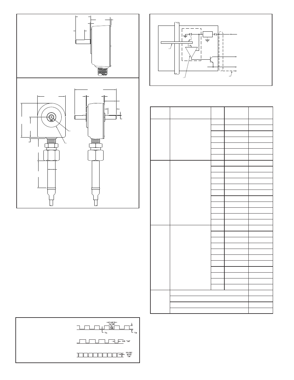
WAVE OUTPUT DIAGRAM
1.65
0.08 (2.03)
0.75
0.04
1.20
MAX.
(30.5)
(41.9)
(1.0)
(19.0)
ZFG DIMENSIONS
In inches (mm)
LED
REGU-
LATOR
RED
WHT
BLK
COMMON
OUTPUT:
8 to 35 VDC @ 50mA max.
V = 30 VDC max.
V = 1V max. @ 40mA
OL
OH
SHAFT
METAL
ETCHED
OPTICAL
DISC
PHOTOLOGIC DETECTOR
AND PULSE SHAPING CIRCUIT
BARE STRANDED SHIELD WIRE
CONNECTED TO INSTRUMENT
COMMON FOR INCREASED
NOISE IMMUNITY
EQUIVALENT CIRCUIT & CONNECTIONS
.75 (19) DIA.
2.75
(69.8)
2.06
(52.3)
2.00
(50.8)
.13 (3.3)
3.38
(85.8)
2.75 (69.9)
4.00 (101.6)
1.65 (41.9)
0.375 (9.52)
DIA. SHAFT
2.00 (50.8) DIA.
.04
(1.0)
.08
(2.03)
MAX.
USABLE SHAFT
LENGTH
1.08 (27.4)
REF., TYP. 2
.75
(19.0)
TYP. 2
.022 (.56)
TYP. 2
ZGG DIMENSIONS In inches (mm)
This is the side view of the
Model ZFG. All other
dimensions (including the
handle tube) are the same
as the Model ZGG. See
below.
ORDERING INFORMATION
MODEL NO.
DESCRIPTION
PPR
OUTPUT
PULSE RATE
CODE
PART NUMBER
ZCG
Rotary Pulse Generator
(Replaces RPGC)
1
ZCG0001C
10
ZCG0010C
12
ZCG0012C
60
ZCG0060C
100
ZCG0100C
*120
ZCG0120C
*200
ZCG0200C
ZFG
Length Sensor
Single Shaft
(Replaces LSCS)
1
1/Foot
ZFG0001C
10
10/Foot
ZFG0010C
12
1/inch
ZFG0012C
20
60/Mt or Yd
ZFG0020C
60
60/Foot
ZFG0060C
100
100/Foot
ZFG0100C
*120
10/Inch
ZFG0120C
*200
600/Mt or Yd
ZFG0200C
.333
1/Mt or Yd
ZFG00/3C
3.333
10/Mt or Yd
ZFG03/3C
33.333
100/Mt or Yd
ZFG33/3C
ZGG
Length Sensor
Double Shaft
(Replaces LSCD)
1
1/Foot
ZGG0001C
10
10/Foot
ZGG0010C
12
1/inch
ZGG0012C
20
60/Mt or Yd
ZGG0020C
60
60/Foot
ZGG0060C
100
100/Foot
ZGG0100C
*120
10/Inch
ZGG0120C
*200
600/Mt or Yd
ZGG0200C
.333
1/Mt or Yd
ZGG00/3C
3.333
10/Mt or Yd
ZGG03/3C
33.333
100/Mt or Yd
ZGG33/3C
RPGFC
Flexible Coupling (1" Length) 0.250" - 0.375"
RPGFC002
Flexible Coupling (1" Length) 0.375" - 0.375"
RPGFC003
Flexible Coupling (1" Length) 0.375" - 0.500"
RPGFC004
Flexible Coupling (1" Length) 0.375" - 6 mm
RPGFC006
2
Square wave output for models
with PPR 1, 10, 12, 20, 60 and
100. Square wave, 50/50 duty
cycle ±10%.
Models that use 1/3 yd. or 1/3 mtr
wheels with internal ÷ 3 circuits.
66/33 duty cycle.
Models with 120 and 200 PPR
utilize internal doubling. (50 μsec
±20% neg. going pulse.)
* Rotary pulse generators and length sensors with 120 & 200 PPR outputs employ
an internal doubling circuit and deliver a fixed 50 μsec ±20% output pulse at the
leading and trailing edge of a passing slot. Additional doubling in external
indicators or circuits may not be applicable. These outputs are derated to 7300
Hz due to internal x2 circuitry. (See Wave Output Diagram)
Notes:
1. For 25 foot cable, replace the last character of the part number (“C”) with “D”.
For 50 foot cable, replace the last character of the part number (“C”) with “E”.
2. Wheels and mounting brackets are sold separately, see Length Sensor Accessories.