Installation, Output wiring, Setpoint adjustment – Red Lion CTS User Manual
Page 2: Trouble shooting, Ordering information
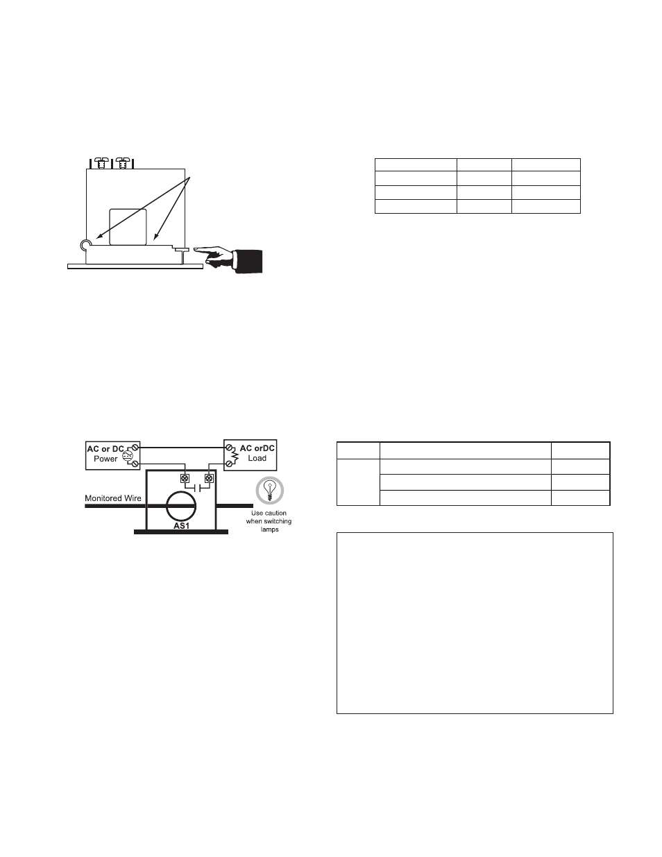
INSTALLATION
Run wire to be monitored through opening in the sensor. The CTS Series
transducers work in the same environment as motors, contactors, heaters, pull-
boxes, and other electrical enclosures. They can be mounted in any position or
hung directly on wires with a wire tie. Just leave at least one inch (25.4 mm)
distance between sensor and other magnetic devices.
Split-Core Versions
Press the tab in the direction as shown to open the sensor. After placing the
wire in the opening, press the hinged portion firmly downward until a definite
click is heard and the tab pops out fully.
KEEP SPLIT-CORE SENSORS CLEAN.
Silicone grease is factory applied on the mating surfaces to prevent rust and
improve performance. Be careful not to allow grit or dirt onto the grease in the
contact area. Operation can be impaired if the mating surfaces do not have good
contact. Check visually before closing.
OUTPUT WIRING
Connect control or monitoring wires to the sensor. Use up to 14 AWG copper
wire and tighten terminals to 5 inch-pounds torque. Be sure the output load does
not exceed the switch rating.
CAUTION: Incandescent lamps can have “Cold Filament Inrush” current of up
to 10 times their rated amperage. Use caution when switching lamps.
SETPOINT ADJUSTMENT
CTS Series SETPOINT is adjusted with a 4-turn potentiometer (CTSS) or a
15-turn potentiometer (CTSF). The pot is shipped factory set to the lowest
setpoint, fully clockwise (CW). Turning the pot counter-clockwise (CCW) will
increase the setpoint. The pot has a slip-clutch to prevent damage at either end
of its rotation. To determine where the adjustment is, turn the pot all the way
CW. This will return it to the minimum setpoint.
Adjustment Notes:
1. Output contacts are solid-state. Check output status by applying voltage to the
contacts and reading the voltage drop across the contacts. An Ohmmeter set
on “Continuity” will give misleading results.
2. It is recommended that the setpoint be adjusted to allow for voltage variations
of 10-15%.
Typical Adjustment
1. Turn the pot to minimum setpoint (4 or 15 turns CW).
2. Have normal operating current running through the sensor. The output
should be tripped since the pot is at its minimum setpoint. For units with
LED, it should be flashing fast (2 to 3 times per second).
3. Turn the pot CCW until the unit un-trips. This is indicated by the slow
flashing of the LED (once every 2 to 3 seconds), or by the changing of
the output switch status.
4. Now turn the pot CW slowly until the unit trips again.
It is now set at the current level being monitored.
A. To Set UNDERLOAD - Turn the pot about 1/8 turn further CW.
B. To Set OVERLOAD - Turn the pot about 1/8 turn further CCW.
TROUBLE SHOOTING
1. Sensor Is Always Tripped
A. The setpoint may be too low. Turn pot CCW to increase setpoint.
B. Switch has been overloaded and contacts are burned out. Check the output
load, remembering to include inrush on inductive loads (coils, motors,
ballasts).
2. Sensor Will Not Trip
A. The setpoint may be too high. Turn pot CW to decrease setpoint.
B. Split Core models: The core contact area may be dirty. Open the sensor and
clean the contact area.
C. Monitored current is below minimum required. Loop the monitored wire
several times through the aperture until the “sensed” current rises above
minimum. Sensed Amps = (Actual Amps) x (Number of Loops). Count
loops on the inside of the aperture.
D. Switch has been overloaded and contacts are burned out. Check the output
load, remembering to include inrush on inductive loads (coils, motors,
ballasts).
Important!
Keep Contact
Area CLEAN!
To Open
Press Tab
Toward Hinge.
DESCRIPTION
PART NUMBERS
CTS
.75 A Fixed-Core Current Switch, Go-No Go
1-150 A Fixed-Core Current Switch, Adjustable
CTSG0000
CTSF0000
CTSS0000
ORDERING INFORMATION
LIMITED WARRANTY
The Company warrants the products it manufactures against defects in materials and
workmanship for a period limited to two years from the date of shipment, provided the
products have been stored, handled, installed, and used under proper conditions. The
Company’s liability under this limited warranty shall extend only to the repair or
replacement of a defective product, at The Company’s option. The Company disclaims
all liability for any affirmation, promise or representation with respect to the products.
The customer agrees to hold Red Lion Controls harmless from, defend, and indemnify
RLC against damages, claims, and expenses arising out of subsequent sales of RLC
products or products containing components manufactured by RLC and based upon
personal injuries, deaths, property damage, lost profits, and other matters which Buyer,
its employees, or sub-contractors are or may be to any extent liable, including without
limitation penalties imposed by the Consumer Product Safety Act (P.L. 92-573) and
liability imposed upon any person pursuant to the Magnuson-Moss Warranty Act (P.L.
93-637), as now in effect or as amended hereafter.
No warranties expressed or implied are created with respect to The Company’s products
except those expressly contained herein. The Customer acknowledges the disclaimers
and limitations contained herein and relies on no other warranties or affirmations.
MODEL NO.
MONITORED AMPS
OUTPUT
SMART-LED
None or OPEN OFF Below Trip Level OPEN SLOW (2 sec) Above Trip Level CLOSED FAST (0.5 sec) 1.75-150 A Split-Core Current Switch, Adjustable Red Lion Controls Red Lion Controls AP Unit 101, XinAn Plaza Building 13, No.99 Tianzhou Road ShangHai, P.R. China 200223 Tel +86 21 6113-3688 Fax +86 21 6113-3683 Red Lion Controls BV Printerweg 10 NL - 3821 AD Amersfoort Tel +31 (0) 334 723 225 Fax +31 (0) 334 893 793
20 Willow Springs Circle
York PA 17406
Tel +1 (717) 767-6511
Fax +1 (717) 764-0839