Safety summary, Meter installation, Installation environment – Red Lion PAX2S User Manual
Page 2: Setting the jumpers, Rear terminals
2
SAFETY SUMMARY
All safety related regulations, local codes and instructions that appear in this
literature or on equipment must be observed to ensure personal safety and to
prevent damage to either the instrument or equipment connected to it. If
equipment is used in a manner not specified by the manufacturer, the protection
provided by the equipment may be impaired. Do not use this unit to directly
command motors, valves, or other actuators not equipped with safeguards. To do
so can be potentially harmful to persons or equipment in the event of a fault to
the unit.
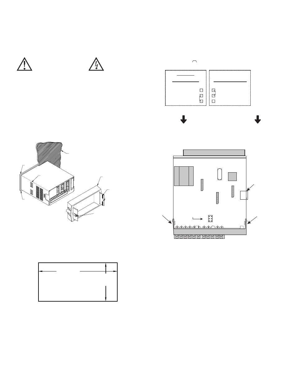
METER INSTALLATION
The PAX2S meets NEMA 4X/IP65 requirements when properly installed.
The unit is intended to be mounted into an enclosed panel. Prepare the panel
cutout to the dimensions shown. Remove the panel latch from the unit. Slide the
panel gasket over the rear of the unit to the back of the bezel. The unit should
be installed fully assembled. Insert the unit into the panel cutout.
While holding the unit in place, push the panel latch over the rear of the unit
so that the tabs of the panel latch engage in the slots on the case. The panel latch
should be engaged in the farthest forward slot possible. To achieve a proper seal,
tighten the latch screws evenly until the unit is snug in the panel (Torque to
approximately 7 in-lbs [79N-cm]). Do not over-tighten the screws.
Installation Environment
The unit should be installed in a location that does not exceed the operating
temperature and provides good air circulation. Placing the unit near devices that
generate excessive heat should be avoided.
SETTING THE JUMPERS
Bridge Excitation
This jumper is used to select bridge excitation voltage level. Use the 5 V
excitation with high output (3 mV/V) bridges, so that the higher sensitivity 24
mV range can be used. Using the 5 V excitation also reduces bridge power
consumption compared to the 10 V excitation. A maximum of four 350 ohm load
cells can be driven by the internal bridge excitation voltage.
CAUTION: Risk of Danger.
Read complete instructions prior to
installation and operation of the unit.
CAUTION:
Risk of electric shock.
PANEL
LATCHING
SLOTS
BEZEL
PANEL
GASKET
PANEL
LATCH
LATCHING
TABS
PANEL
MOUNTING
SCREWS
-.00
(92 )
-.0
+.8
3.62
+.03
(45 )
1.77
-.0
+.5
-.00
+.02
PANEL CUT-OUT
10V
5V
±240mV
±24mV
INPUT RANGE
BRIDGE
EXCITATION
REAR TERMINALS
JUMPER SELECTIONS
The
indicates factory setting.
Main Circuit Board
REAR TERMINALS
FRONT DISPLAY
JUMPER
LOCATION
Finger
Tab
Finger
Tab
USB
Connector