Wiring connections, Cub4lp/cl signal input, Offset adjustments – Red Lion CUB4LP User Manual
Page 3: Span adjustments, Emc installation guidelines, Backlight power (cub4cl only)
3
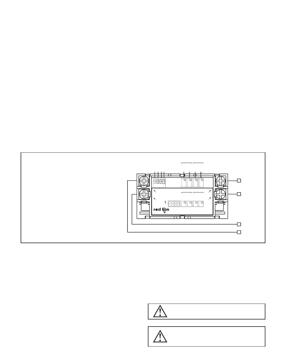
WIRING CONNECTIONS
All conductors should meet voltage and current ratings for
each terminal. Also cabling should conform to appropriate
standards of good installation, local codes and regulations. It is
recommended that power supplied to the unit (AC or DC) be
protected by a fuse or circuit breaker.
The electrical connections are made via screw-clamp terminals
located on the back of the unit. When wiring the unit, use the
label to identify the wire position with the proper function. Strip
the wire, leaving approximately ¼" of bare wire (stranded wires
should be tinned with solder). Insert the wire into the screw-
clamp terminal and tighten the screw until the wire is clamped
tightly. Each terminal can accept up to two #14 AWG wires.
4
2
1
3
VDC +
SIG +
COM
SIG -
(SENSOR)
(CL ONLY)
(CL ONLY)
(SENSOR)
(CL)
(CL)
V+
SIG.+
1 COM
SIG.-
4
2
4
3
2
1
ON
0.000
0.00
0.0
10-5
0
FIN
E
CUB4LP/CL
3
COA
RSE
COA
RSE
FIN
E
SPAN
OFFSET
1 2 3 4
SPAN
OFFSET
COA
RSE
FIN
E
COA
RSE
FIN
E
0.0
0.00
0.000
10-5
0
RED LION CONTROLS
YORK, PA. MADE IN U.S.A.
M1721C
CUB4LP/CL SIGNAL INPUT
The current range is selected by setting DIP switch S1 to the OFF position
for a 4 to 20 mA input or ON for a 10 to 50 mA input. Attach the signal wires
to terminals 3 (SIG-) and 4 (SIG+) observing the correct polarity. The (SIG-)
signal input circuit is not reverse polarity protected.
Backlight Power (CUB4CL only)
Attach a 9 to 28 VDC supply to terminals 1 (COM) and 2 (V+) to power the
backlight. Terminals 3 (SIG-) and 1 (COM) are AC coupled with a capacitor.
This limits the isolation between these terminals to 50 VDC maximum.
OFFSET ADJUSTMENTS
The minimum currents are not zero based with 4 to 20 mA and 10 to 50 mA
signals. To obtain a zero minimum display reading, the display must be offset.
The display on the CUB4LP/CL can be offset by adjusting the Coarse and Fine
Offset pots.
SPAN ADJUSTMENTS
Span is defined as the numerical range that the display traverses, disregarding
the decimal point, when the input signal is varied from minimum to maximum
(4 to 20 mA or 10 to 50 mA). For example; if a unit is to display 250 @ 4 mA
and 1000 @ 20 mA, the span is 750 (the difference between 250 and 1000). Had
the minimum display been -250, the span would be 1250 (1000 - (-250) = 1250).
The CUB4LP/CL can be set to operate over a wide span range by adjusting the
Coarse and Fine Span adjustment pots. The Coarse Span pot is used to get the
display to within a couple of counts of the desired reading, and the Fine Span
pot is used to adjust for the exact reading.
WARNING - EXPLOSION HAZARD - DO NOT DISCONNECT
EQUIPMENT UNLESS POWER HAS BEEN SWITCHED OFF
OR THE AREA IS KNOWN TO BE NON-HAZARDOUS.
THIS EQUIPMENT IS SUITABLE FOR USE IN:
Class I, Division 2, Groups A, B, C, and D
Class II, Division 2, Groups F and G
Class III, Division 2 or Non Hazardous locations.
EMC INSTALLATION GUIDELINES
Although Red Lion Controls Products are designed with a high degree of
immunity to Electromagnetic Interference (EMI), proper installation and wiring
methods must be followed to ensure compatibility in each application. The type
of the electrical noise, source or coupling method into a unit may be different
for various installations. Cable length, routing, and shield termination are very
important and can mean the difference between a successful or troublesome
installation. Listed are some EMI guidelines for a successful installation in an
industrial environment.
1. A unit should be mounted in a metal enclosure, which is properly connected
to protective earth.
2. Use shielded cables for all Signal and Control inputs. The shield connection
should be made as short as possible. The connection point for the shield
depends somewhat upon the application. Listed below are the recommended
methods of connecting the shield, in order of their effectiveness.
a. Connect the shield to earth ground (protective earth) at one end where the
unit is mounted.
b. Connect the shield to earth ground at both ends of the cable, usually when
the noise source frequency is over 1 MHz.
3. Never run Signal or Control cables in the same conduit or raceway with AC
power lines, conductors, feeding motors, solenoids, SCR controls, and
heaters, etc. The cables should be run through metal conduit that is properly
grounded. This is especially useful in applications where cable runs are long
and portable two-way radios are used in close proximity or if the installation
is near a commercial radio transmitter. Also, Signal or Control cables within
an enclosure should be routed as far away as possible from contactors, control
relays, transformers, and other noisy components.
4. Long cable runs are more susceptible to EMI pickup than short cable runs.
5. In extremely high EMI environments, the use of external EMI suppression
devices such as Ferrite Suppression Cores for signal and control cables is
effective. The following EMI suppression devices (or equivalent) are
recommended:
Fair-Rite part number 0443167251 (RLC part number FCOR0000)
Line Filters for input power cables:
Schaffner # FN2010-1/07 (Red Lion Controls # LFIL0000)
6. To protect relay contacts that control inductive loads and to minimize radiated
and conducted noise (EMI), some type of contact protection network is
normally installed across the load, the contacts or both. The most effective
location is across the load.
a. Using a snubber, which is a resistor-capacitor (RC) network or metal oxide
varistor (MOV) across an AC inductive load is very effective at reducing
EMI and increasing relay contact life.
b. If a DC inductive load (such as a DC relay coil) is controlled by a transistor
switch, care must be taken not to exceed the breakdown voltage of the
transistor when the load is switched. One of the most effective ways is to
place a diode across the inductive load. Most RLC products with solid state
outputs have internal zener diode protection. However external diode
protection at the load is always a good design practice to limit EMI.
Although the use of a snubber or varistor could be used.
RLC part numbers: Snubber: SNUB0000
Varistor: ILS11500 or ILS23000
7. Care should be taken when connecting input and output devices to the
instrument. When a separate input and output common is provided, they
should not be mixed. Therefore a sensor common should NOT be connected
to an output common. This would cause EMI on the sensitive input common,
which could affect the instrument’s operation.
Visit RLC’s web site at http://www.redlion.net/Support/InstallationConsiderations.
html for more information on EMI guidelines, Safety and CE issues as they
relate to Red Lion Controls products.