Power supply requirements, Communicating with the xcdn option card, Devicenet port protocols – Red Lion XCDN User Manual
Page 3: Xcdn port pin outs, Software/unit operations, Crimson software, Troubleshooting your xcdn option card
POWER SUPPLY REQUIREMENTS
NEW AND EXISTING INSTALLATIONS
The XCDN option card draws all of its power from the main board of the
Modular Controller Master or Data Station Plus. The specifications of the
Modular Controller Master or Data Station Plus account for the power needs of
an option card.
COMMUNICATING WITH THE XCDN OPTION CARD
CONFIGURING A XCDN OPTION CARD
The XCDN is configured using Crimson software. Crimson is available as a
free download from www.redlion.net, or it can be ordered on CD. Updates to
Crimson for new features and drivers are posted on the website as they become
available. By configuring the XCDN using the latest version of Crimson, you
are assured that your unit has the most up-to-date feature set. Crimson software
can configure the XCDN through the RS232 PGM port, USB port, Ethernet
port, or CompactFlash socket on your Modular Controller Master or Data
Station Plus. Additional information can be found in your Modular Controller
Master or Data Station Plus hardware bulletin and the Crimson user manual.
DeviceNet PORT PROTOCOLS
The XCDN option card has one DeviceNet port. This port may be configured
for various DeviceNet protocols. Check www.redlion.net for currently supported
protocols.
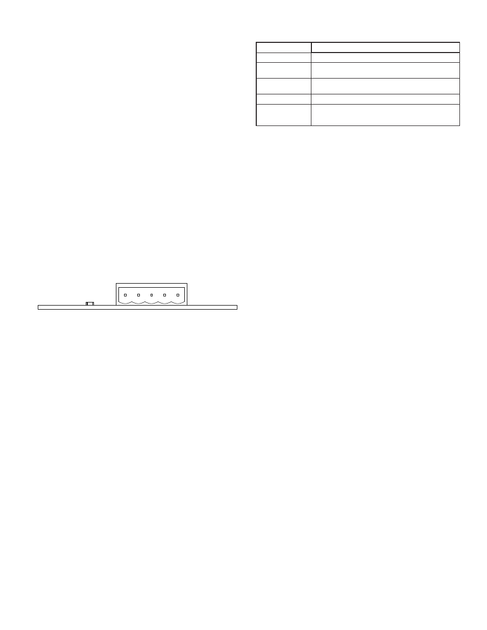
XCDN PORT PIN OUTS
Must use only NEC Class 2 or Limited Power Source (LPS) rated power
supply.
V-
Position 1 of the pluggable connector provides a CAN ground connection.
This terminal is isolated from the Modular Controller Master and Data Station
Plus.
CAN_L
Position 2 of the pluggable connector provides the CAN_L bus line (active
low). This terminal is isolated from the Modular Controller Master and Data
Station Plus.
DRAIN (OPTIONAL)
Position 3 of the pluggable connector is provided for optional drain
connections. This position is available only to tie drain wires together or to earth
ground. There is no internal connection to earth ground. The DRAIN position is
not connected to any circuitry internal to the XCDN option card or Modular
Controller Master and Data Station Plus.
CAN_H
Position 4 of the pluggable connector provides the CAN_H bus line (active
high). This terminal is isolated from the Modular Controller Master and Data
Station Plus.
V+ (OPTIONAL 24 VDC)
Position 5 of the pluggable connector is provided for optional 24 VDC
connections. This position is available only to tie 24 VDC wires together. The
XCDN card neither provides 24 VDC power nor uses 24 VDC power through
this connection. The V+ position is not connected to any circuitry internal to the
XCDN option card or Modular Controller Master and Data Station Plus.
SOFTWARE/UNIT OPERATIONS
LED
CRIMSON SOFTWARE
Crimson 2.0 software is available as a free download from www.redlion.net
or it can be purchased on a CD, see "Ordering Information" for part number. The
latest version of the software is always available from the web site, and updating
your copy is free.
TROUBLESHOOTING YOUR XCDN OPTION CARD
If for any reason you have trouble operating, connecting, or simply have
questions concerning your new XCDN option card, contact Red Lion’s technical
support. For contact information, refer to the back page of this bulletin for phone
and fax numbers.
EMAIL: [email protected]
Web Site: http://www.redlion.net
3
LED STATE
XCDN CARD INDICATION
OFF
Initializing
FLASHING GREEN
GREEN
FLASHING RED
One or more established communications have timed out
RED
The device is online and is waiting on communications
from other devices
The device is online and has established
communications with another device
The device has detected an error that has rendered it
incapable of communicating on the network (duplicate
MAC ID or bus activity).
LED
DRAIN
V+
V-
CAN_L
CAN_H