G3rs o, Pecifications, Nstalling – Red Lion G3RS User Manual
Page 2: Ption, The option card label, Power supply requirements, Installation instructions
2
1. POWER REQUIREMENTS:
Power is supplied to the option card from the main board of your G3 operator
interface.
2. COMMUNICATIONS:
Serial Ports: Format and Baud Rates for each port are individually software
programmable up to 115,200 baud and are isolated to help prevent ground
loops. The RS422/485 and DH485 port via RJ45 and the RS232 port via
RJ12 share the same hardware. The G3RS option card multiplexes the
ports to communicate via two protocols. These ports may be used to
configure different master protocols, but only one port may be used if
configuring a slave protocol or AB DH485.
DH485 TXEN: Transmit enable; open collector, V
OH
= 15 VDC, V
OL
= 0.5
Isolation from G3RS Communication ports to G3 operator interface:
1000 VDC for 1 minute.
3. CERTIFICATIONS AND COMPLIANCES:
ELECTROMAGNETIC COMPATIBILITY
Emissions and Immunity to EN 61326: Electrical Equipment for Measurement,
Control and Laboratory use.
Immunity to Industrial Locations: Reference G3 unit for emissions and
immunity specifications
4. ENVIRONMENTAL CONDITIONS:
Operating Temperature Range: 0 to 50 °C
Storage Temperature Range: -20 to 80 °C
Operating and Storage Humidity: 80% maximum relative humidity (non-
condensing) from 0 to 50 °C.
Altitude: Up to 2000 meters.
5. CONSTRUCTION: Installation Category I, Pollution Degree 2.
6. INSTALLATION REQUIREMENTS: Card must be installed inside the
rear cover of a G3 operator interface with the hardware provided. See
“Installing the G3RS Option Card” for more details.
S
PECIFICATIONS
+
-
ISOLATING
DC : DC
A
RS422
PORT
PORT
RS232
B
B
RS485/
BLOCK DIAGRAM
I
NSTALLING
THE
G3RS O
PTION
C
ARD
THE OPTION CARD LABEL
Place the option card label on your rear cover in the space indicated by the
dashed lines and labeled “COMMS EXPANSION MODULE.”
POWER SUPPLY REQUIREMENTS
NEW AND EXISTING INSTALLATIONS
The G3RS option card draws all of its power from the main board of your G3
operator interface. The specifications of your G3 operator interface account for
the power needs of an option card.
COMMS EXP
ANSION MODULE
RS232
RS485
RS232
INSTALLATION INSTRUCTIONS
Caution: The option and main circuit boards contain static sensitive components.
Before handling the cards, discharge static charges from your body
by touching a grounded bare metal object. Ideally, handle the cards at
a static controlled clean workstation. Also, handle the cards by the
edges only. Dirt, oil, or other contaminants that may contact the cards
can adversely affect circuit operation.
Warning: Depending upon the G3 operator interface, high voltage may
be present inside the operator interface. Be sure to remove all power
before removing the rear cover of the operator interface.
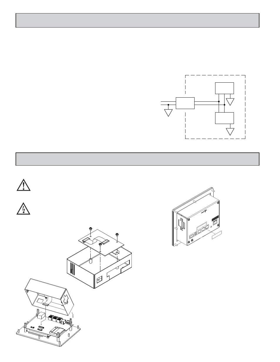
Each G3RS option card comes with a cable for communications and three
screws for attaching the option card to the inside of the G3 operator interface’s
rear cover.
To install the option card remove all power
and I/O communications cables from the
unit. The G3 operator interface literature
contains instructions for removing the rear
cover, refer to the “Battery & Time
Keeping” section.
Using the three screws
provided connect the option card
to the rear cover as shown in
Figure 1.
Connect the cable from the option
card to CN11 on the main board of the
G3 operator interface as shown in
Figure 2. Be sure both ends of the
cables are firmly seated into their
appropriate connector housing.
Carefully replace the rear cover
by reversing the instructions for
removing the rear cover.
Figure 2
Figure 1