G303, Nstalling, Owering – Red Lion G303 3" Monochrome Operator Panel User Manual
Page 3: User identifiable keys, Mounting instructions, Connecting to earth ground, Power supply requirements
3
i
nStalling
and
p
owering
the
g303
USER IDENTIFIABLE KEYS
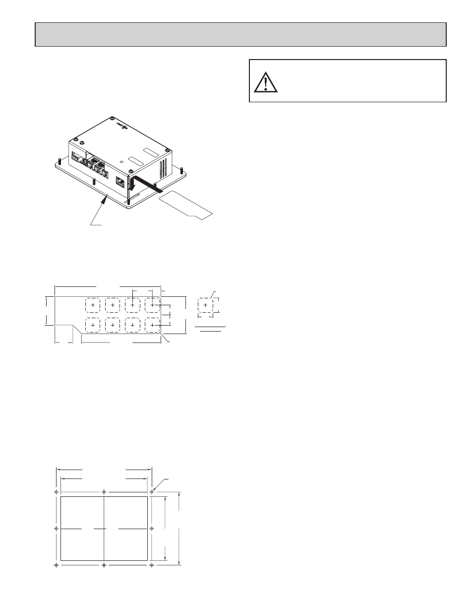
The G303 unit comes with a pre-printed key strip inserted. This key strip is
labeled F1 through F8 and corresponds to Crimson software.
If desired, these keys may be custom labeled for specific functions. The
default key strip may be removed and a custom key strip inserted. Each unit is
delivered with two sheets of white “Cover 65” paper. This 8½ x11 paper may be
used with most copiers, jet printers, or laser printers.
Custom key strips are made easily using the Adobe Acrobat file available
from www.redlion.net or included with each Crimson CD. This program allows
users to enter custom text and color schemes.
If more customization is needed, a graphics package can be used. The key
strip dimensions are as follows.
When inserting the key strip into the slot in the G303 panel, start one corner
first then slowly insert the strip into place.
Note: Key strips need to be inserted into the unit before mounting into a
panel.
MOUNTING INSTRUCTIONS
This operator interface is designed for through-panel mounting. A panel cut-
out diagram and a template are provided. Care should be taken to remove any
loose material from the mounting cut-out to prevent that material from falling
into the operator interface during installation. A gasket is provided to enable
sealing to NEMA 4X/IP66 specification. Install the eight kep nuts provided and
tighten evenly for uniform gasket compression.
Note: tightening the kep nuts beyond a maximum of 17 inch-pounds (1.92
N-m) may cause damage to the front panel.
CONNECTING TO EARTH GROUND
Each G303 has a chassis ground terminal on the back of the unit. Your unit
should be connected to earth ground (protective earth).
The chassis ground is not connected to signal common of the unit.
Maintaining isolation between earth ground and signal common is not required
to operate your unit. But, other equipment connected to this unit may require
isolation between signal common and earth ground. To maintain isolation
between signal common and earth ground care must be taken when connections
are made to the unit. For example, a power supply with isolation between its
signal common and earth ground must be used. Also, plugging in a USB cable
may connect signal common and earth ground.
1
1. USB’s shield may be connected to earth ground at the host. USB’s shield in
turn may also be connected to signal common.
POWER SUPPLY REQUIREMENTS
The G303 requires a 24 VDC power supply rated at 9.5 W. Your unit may
draw considerably less than 9.5 W depending upon the options being used. As
additional features are used your unit will draw increasing amounts of power.
Items that could cause increases in current are additional communications,
optional communications card, Compact Flash card, and other features
programmed through Crimson.
In any case, it is very important that the power supply is mounted correctly if
the unit is to operate reliably. Please take care to observe the following points:
– The power supply must be mounted close to the unit, with usually not
more than 6 feet (1.8 m) of cable between the supply and the operator
interface. Ideally, the shortest length possible should be used.
– The wire used to connect the operator interface’s power supply should
be at least 22-gage wire. If a longer cable run is used, a heavier gage
wire should be used. The routing of the cable should be kept away from
large contactors, inverters, and other devices which may generate
significant electrical noise.
– A power supply with a Class 2 or SELV rating is to be used. A Class 2
or SELV power supply provides isolation to accessible circuits from
hazardous voltage levels generated by a mains power supply due to
single faults. SELV is an acronym for “safety extra-low voltage.” Safety
extra-low voltage circuits shall exhibit voltages safe to touch both under
normal operating conditions and after a single fault, such as a
breakdown of a layer of basic insulation or after the failure of a single
component has occurred.
REMOVE PANEL GASKET
BEFORE REMOVING OR
INSERTING KEY STRIPS
.675
3.00 (76.2)
1.075
4.00 (101.6)
3X .75
CHAMFER (2 PLCS)
FOR EASIER INSERTION
R.100
.375 (9.5)
(35.6)
.375 (9.5)
EIGHT KEYS
VISIBLE AREA OF
.55
.325
.55
(27.3)
(17.1)
1.40
(14)
(14)
(8.3)
6.25 (158.8)
4.625
(117.5)
8X Ш.188 (Ш4.8)
5.275
(134)
6.875 (174.6)
All tolerances ±0.010" (±0.25 mm).
ALL NONINCENDIVE CIRCUITS MUST BE WIRED USING
DIVISION 2 WIRING METHODS AS SPECIFIED IN ARTICLE 501-4
(b), 502-4 (b), AND 503-3 (b) OF THE NATIONAL ELECTRICAL
CODE, NFPA 70 FOR INSTALLATION WITHIN THE UNITED
STATES, OR AS SPECIFIED IN SECTION 19-152 OF CANADIAN
ELECTRICAL CODE FOR INSTALLATION IN CANADA.