Block diagram for gmtc8, gmrtd6, gmini8 & gminv8, Gminv8 specifications, Gmini8 specifications – Red Lion GMTC/GMRTD Modules for Thermocouples and RTDs User Manual
Page 3
3
GMINV8 SPECIFICATIONS
21. INPUTS:
Channels: 8 single-ended
Ranges: 0-10 VDC or ±10 VDC
Effective Resolution: Full 16-bit
Programmable Scaling: ±30,000
Sample Time: 50 msec - 400 msec, depending on number of enabled inputs.
ENABLED
INPUTS
SCAN TIME
(READING RATE)
1
50 msec (20 Hz)
2
100 msec (10 Hz)
3
150 msec (6.7 Hz)
4
200 msec (5 Hz)
5
250 msec (4 Hz)
6
300 msec (3.3 Hz)
7
350 msec (2.9 Hz)
8
400 msec (2.5 Hz)
Common Mode Rejection: >110 dB, 50/60 Hz
Normal Mode Rejection: >90 dB, 50/60 Hz
Step Response Time: One scan time (to within 99% of final value)
Input Impedance: 10 M Ω
Max. Continuous Overload: 50 V
22. ACCURACY: ±0.1% of span
23. INPUT FAULT RESPONSE: Upscale Drive, Input Fault Alarm bit set
high, ALM LED illuminates below -10.4 VDC and above +10.4 VDC.
GMINI8 SPECIFICATIONS
18. INPUTS:
Channels: 8 single-ended
Ranges: 0-20 mA or 4-20 mA
Effective Resolution: Full 16-bit
Programmable Scaling: ±30,000
Sample Time: 50 msec - 400 msec, depending on number of enabled inputs.
ENABLED
INPUTS
SCAN TIME
(READING RATE)
1
50 msec (20 Hz)
2
100 msec (10 Hz)
3
150 msec (6.7 Hz)
4
200 msec (5 Hz)
5
250 msec (4 Hz)
6
300 msec (3.3 Hz)
7
350 msec (2.9 Hz)
8
400 msec (2.5 Hz)
Common Mode Rejection: >110 dB, 50/60 Hz
Normal Mode Rejection: >90 dB, 50/60 Hz
Step Response Time: One scan time (to within 99% of final value)
Input Impedance: 10 Ω
Max. Continuous Overload: 100 mA
19. ACCURACY: ±0.1% of span
20. INPUT FAULT RESPONSE: Upscale Drive, Input Fault Alarm bit set
high, ALM LED illuminates below -3 mA, and above 23 mA for 0-20 mA
range; below +3 mA and above 23 mA for 4-20 mA signals.
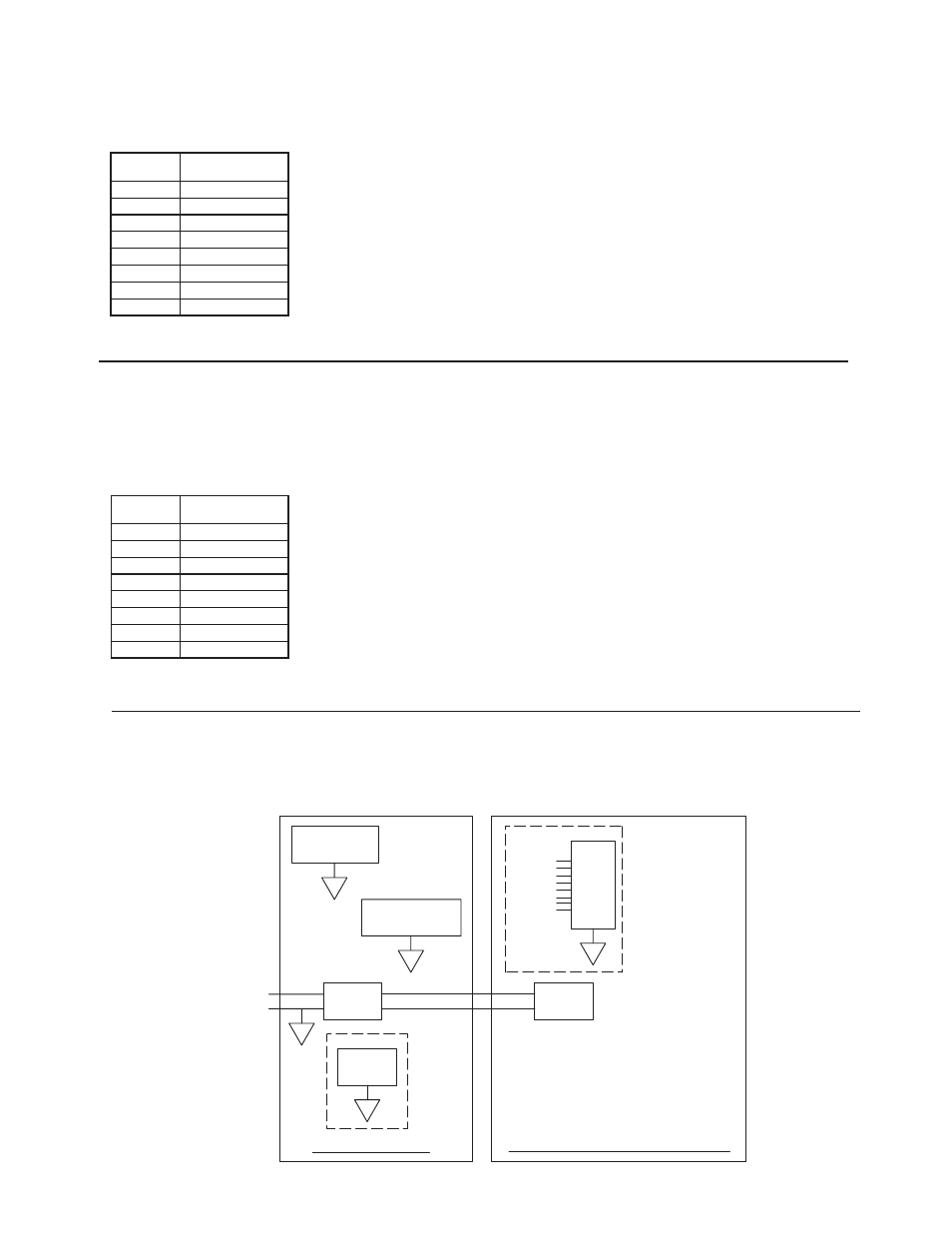
PORT 3
ETHERNET
B
ISOLATED
A
POWER
SUPPLY
+
-
24VDC
GRAPHITE HMI
GMTC8, GMRTD6, GMINI8, GMINV8
PORT 2
A
COMMUNICATIONS
A
PORT 1
PROGRAMMING
C
ISOLATED
POWER
SUPPLY
INPUTS
BLOCK DIAGRAM FOR
GMTC8, GMRTD6, GMINI8 & GMINV8