Specifications, Block diagram – Red Lion GMOUT 4 Channel Analog Output Module User Manual
Page 2
2
SPECIFICATIONS
1. POWER: Power will be supplied by the Graphite host device.
2. LEDs:
STS - Status LED shows module condition.
ALM - Alarm LED is lit when an internal alarm condition exists.
3. MEMORY: Non-volatile memory retains all programmable parameters.
4. COMMUNICATIONS: Provided by the graphite host device
4. OUTPUTS:
Channels: 4 independent outputs
Response Time: 25 msec max. to within 99% of final value
Output Range: software selectable
OUTPUT RANGE
ACCURACY *
18 to 28
°
C
10 to 75% RH
ACCURACY *
-40 to 75
°
C
0 to 85% RH
COMPLIANCE RESOLUTION
0 to 5 VDC
0.2% of span 0.4% of span
10K Ω min.
1/30,000
0 to 10 VDC
0.1% of span 0.2% of span
10K Ω min.
1/60,000
-10 to +10 VDC 0.1% of span 0.2% of span
10K Ω min.
1/60,000
0 to 20 mA
0.1% of span 0.2% of span
500 Ω max.
1/60,000
4 to 20 mA
0.1% of span 0.2% of span
500 Ω max.
1/48,000
* The accuracy is specified after 20 minutes warmup; in a non-condensing
environment; and includes linearity errors.
5. ISOLATION LEVEL: The outputs are isolated from each other, and are
isolated from the power supply. 500 V @ 50/60 Hz for 1 minute between any
of the outputs and the Host power supply input.
6. ENVIRONMENTAL CONDITIONS:
Operating Temperature Range: -40 to +75 °C; limited to host
Storage Temperature Range: -40 to +85 °C
Operating and Storage Humidity: 85% max relative humidity, non-
condensing, from -40 to +75 °C
Altitude: Up to 2000 meters
7. CERTIFICATIONS AND COMPLIANCES:
CE Approved
EN 61326-1 to Industrial Locations
IEC/EN 61010-1
RoHS Compliant
UL Listed: File #E302106
8. CONSTRUCTION: Case body is all metal construction. For indoor use only.
Installation Category II, Pollution Degree 2.
9. CONNECTIONS: Removable wire clamp screw terminal blocks.
Wire Gage: 28-16 AWG terminal gage wire
Torque: 6.0 lbf-inch (96 oz-inch)
10. MOUNTING: Screws to host
11. WEIGHT: 8 oz (224 g)
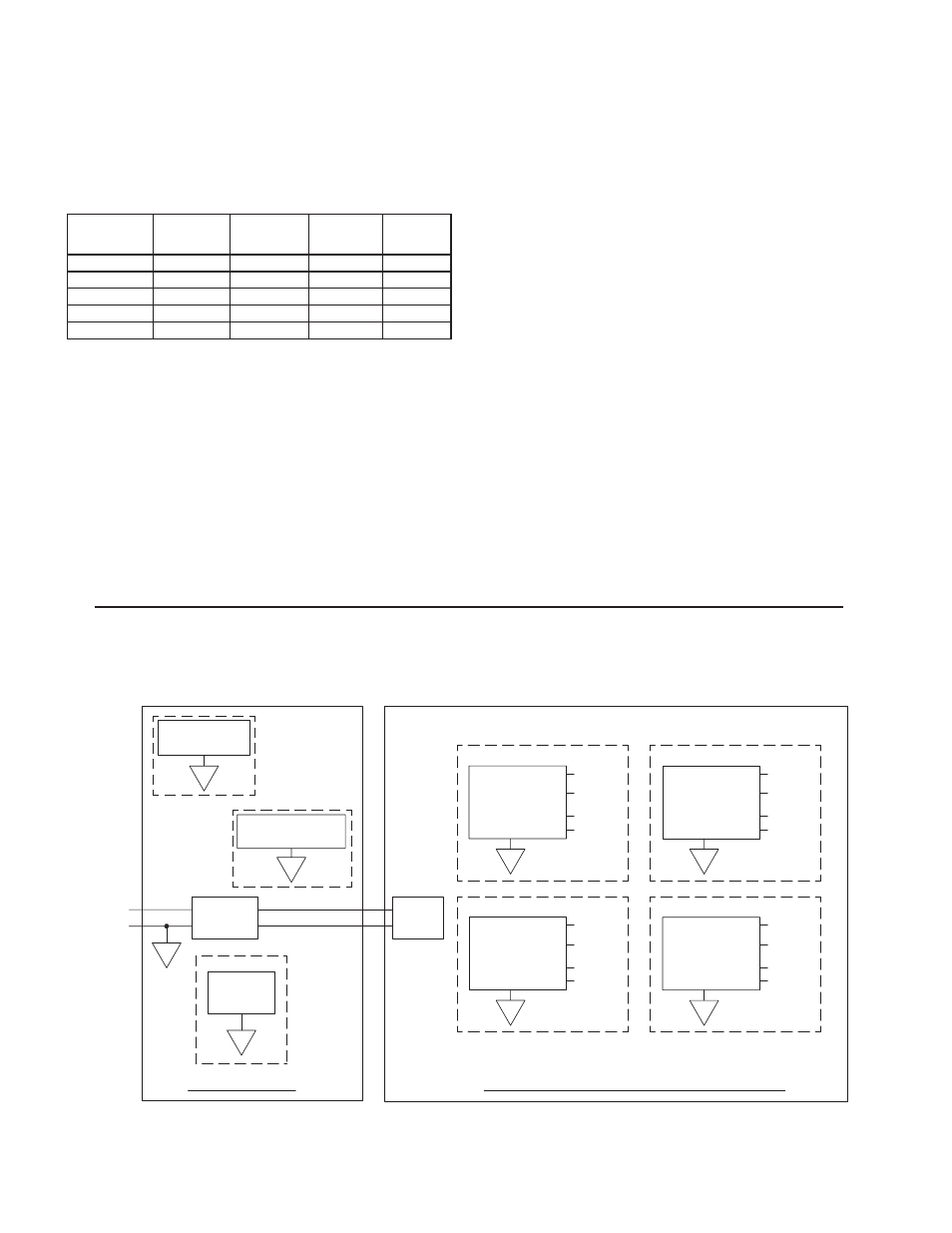
PORT 3
ETHERNET
B
ISOLATED
A
POWER
SUPPLY
+
-
VDC
GRAPHITE HOST
GMOUT400 - ANALOG OUTPUT MODULE
PORT 2
A
COMMUNICATIONS
A
PORT 1
PROGRAMMING
POWER
SUPPLY
C
OUTPUT
CHANNEL 1
4-20mA
0-5V
+/-10V
0-20mA
ISOLATED
V+
V-
I+
I-
0-10V
V-
+/-10V
E
OUTPUT
0-20mA
4-20mA
I+
I-
ISOLATED
CHANNEL 3
0-5V
0-10V
V+
I-
4-20mA
F
ISOLATED
CHANNEL 4
OUTPUT
0-10V
0-20mA
+/-10V
I+
V-
0-5V
V+
V-
+/-10V
D
OUTPUT
0-20mA
4-20mA
I+
I-
ISOLATED
CHANNEL 2
0-5V
0-10V
V+
BLOCK DIAGRAM