D-9 connector – Vaisala PTB330 User Manual
Page 33
Chapter 3 _______________________________________________________________ Installation
VAISALA _______________________________________________________________________ 31
D-9 Connector
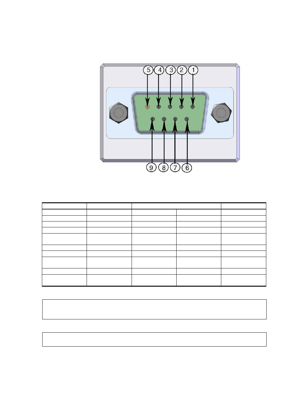
Figure 19
Wiring of Optional D-9 Connector
Table 4
Pin Assignments to RS-232/485 Serial Output
Pin
Wire Color
Serial Signal
Analog Signal
RS-232 (EIA-232) RS-485 (EIA-485)
1 Red
2 White
TX
TX
3 Black
RX
RX
4 (optional)
Yellow
External power
control
External power
control
External power
control
5 Brown
Ground
Ground
6 Green
D0-
(Lo)
Aout
7 Blue
Ground
for
supply
voltage
Ground for supply
voltage
Ground for supply
voltage
8 Grey
D1+
(Hi)
AGND
9 Orange
Supply
voltage
(10...30 VDC)
Supply voltage
(10...30 VDC)
Supply voltage
(10...30 VDC)
NOTE
The D-9 connector cannot be used with relay modules or power
supply modules that have AC (mains) power connection.
NOTE
The D-9 connector is not IP65 protection classified.