Signal and power supply wiring – Vaisala PTB330 User Manual
Page 30
USER'S GUIDE____________________________________________________________________
28 __________________________________________________________________ M210855EN-D
Signal and Power Supply Wiring
When wiring the power supply module, see section AC Power Supply
Module on page 32.
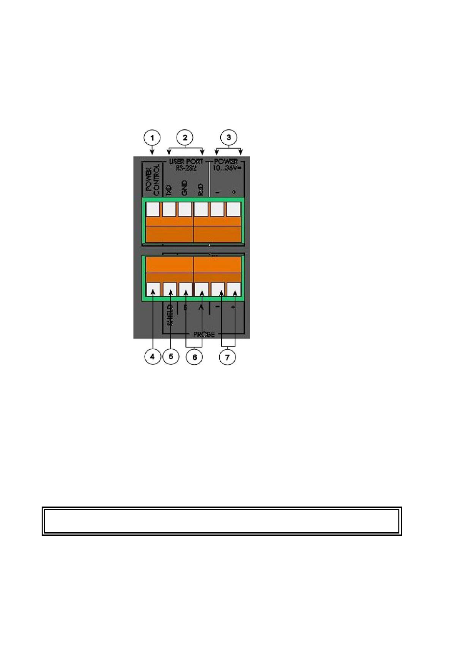
Figure 17
Screw Terminal Block on Motherboard
Numbers refer to Figure 17 above:
1
= Power control (0VDC = OFF, 5VDC = ON, if feature enabled)
2
= User port (RS-232 terminals)
3
= Power supply terminals 10 ... 36 V DC
4
= Test terminal (not connected, not used in PTB330)
5
= Probe cable shield (not used in PTB330)
6
= Probe bus (not used in PTB330)
7
= Probe power (not used in PTB330)
WARNING
Make sure that you connect only de-energized wires.
See also other documents in the category Vaisala Tools:
- DM500 (138 pages)
- DM70 (93 pages)
- DMT132 (74 pages)
- DMT143 (76 pages)
- DMT152 (70 pages)
- DMT242 (4 pages)
- DMT340 (191 pages)
- DMT345 (185 pages)
- DPT145 (63 pages)
- DPT146 (71 pages)
- PTU300 (217 pages)
- PTB330TS (89 pages)
- PTB220 (113 pages)
- PTB220 (10 pages)
- PTU200 (64 pages)
- PTU200MIK1 (18 pages)
- SPH10 (2 pages)
- SPH20 (2 pages)
- PTB110 (4 pages)
- PTB200 (30 pages)
- PTB210 (analog) (27 pages)
- PTB210 (serial) (32 pages)
- GM70 (68 pages)
- GMD20 (4 pages)
- GMK220 (18 pages)
- GML20 (2 pages)
- GML20T (2 pages)
- GMM20W (5 pages)
- GMM220 (6 pages)
- GMP231 (2 pages)
- GMP231 (90 pages)
- GMP343 (94 pages)
- GMR20 (2 pages)
- GMT220 (42 pages)
- GMW90 (101 pages)
- XMW90 (4 pages)
- MM70 (67 pages)
- MM70 (71 pages)
- MMT162 (66 pages)
- MMT310 (81 pages)
- MMT330 (181 pages)
- MMT330 (171 pages)