Wiring, Figure 8, Dmt143 digital and analog connectors – Vaisala DMT143 User Manual
Page 24: Figure 9, Wiring the digital connector, Figure 10, Wiring the analog connector, Table 5, Connector pinouts, Caution
USER'S GUIDE ____________________________________________________________________
22 ___________________________________________________________________ M211435EN-E
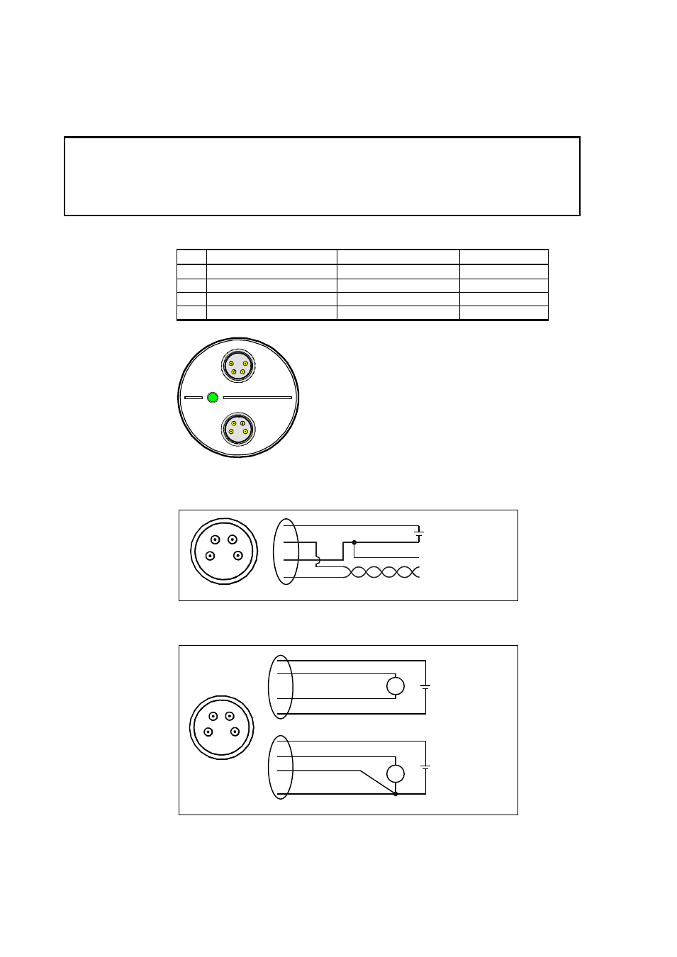
Wiring
CAUTION
The power supply lines are internally connected. You can use either one
of them, but do not connect more than one supply voltage in permanent
installations. Temporary simultaneous use with the USB service cable or
DM70 hand-held dewpoint meter (which also provide power) is OK.
Table 5
Connector Pinouts
Pin Analog connector
Digital connector
Wire color
1
VDC supply+
VDC supply+
Brown
2
Ch-
RS-485 D0-
White
3
GND
GND
Blue
4
Ch+
RS-485 D1+
Black
1202-129
Figure 8
DMT143 Digital and Analog Connectors
1202-127
Figure 9
Wiring the Digital Connector
1202-128
Figure 10
Wiring the Analog Connector
Digital
Analog
2
4
1
3
12 ... 28 VDC
RS-485 +
RS-485 -
GND
1
2
3
4
+
-
+
-
1
3
4
2
mA
+
-
1
3
4
2
V
18 ... 28 VDC
12 ... 28 VDC
2
4
1
3
+
-
+
-