Wiring diagrams – Vaisala HMT140 User Manual
Page 27
Wiring Diagrams
M21488EN-C
19
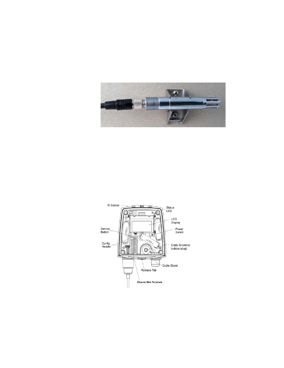
Installing the entire probe in the measurement environment
prevents heat conduction to the sensor, and is the
recommended installation method.
Figure 8: Optional Probe Mounting Clamp
CAUTION: Attaching the probe mounting clamp to a con-
ductive wall material should be avoided, since
the potential galvanic connection to the power
supplies and uncontrolled earth current loops
could cause measurement errors or even dam-
age to an HMT140 transmitter (not the HMT141).
Wiring Diagrams
The following figures outline the components, wiring and
connections of the HMT140.
Figure 9: HMT140 Components Diagram
See also other documents in the category Vaisala Humidifiers:
- Calibration of Digital Transmitters with HMI41 (36 pages)
- Calibration of Series HMDW2030 and HMP130 Transmitter with HMI41 (14 pages)
- Calibration of Series HMDW6070 and HMP140 Transmitter with HMI41 (30 pages)
- HM34 (30 pages)
- HM40 (47 pages)
- HM44 (52 pages)
- HM70 (83 pages)
- HMD40 (1 page)
- HMD60 (4 pages)
- HMD70 (18 pages)
- HMDW110 (62 pages)
- HMDW80 (51 pages)
- HMI41 (74 pages)
- HMP41 (72 pages)
- HMK15 (39 pages)
- HMM100 (71 pages)
- HMM105 (23 pages)
- HMM211 (42 pages)
- HMM212 (36 pages)
- HMM213 (52 pages)
- HMP140 (28 pages)
- HMP155 (84 pages)
- HMP228 (115 pages)
- HMP230 (163 pages)
- HMP240 (130 pages)
- HMP260 (118 pages)
- HMP60 (71 pages)
- HMT100 (52 pages)
- HMT120 (87 pages)
- HMT130 (95 pages)
- HMT310 (88 pages)
- HMT310 (105 pages)
- HMT330 (209 pages)
- HMT360 (97 pages)
- HMT360 (63 pages)
- HMT360N (110 pages)
- HMW40 (1 page)
- HMW90 (110 pages)
- SHM40 (68 pages)
- RDP100 (14 pages)